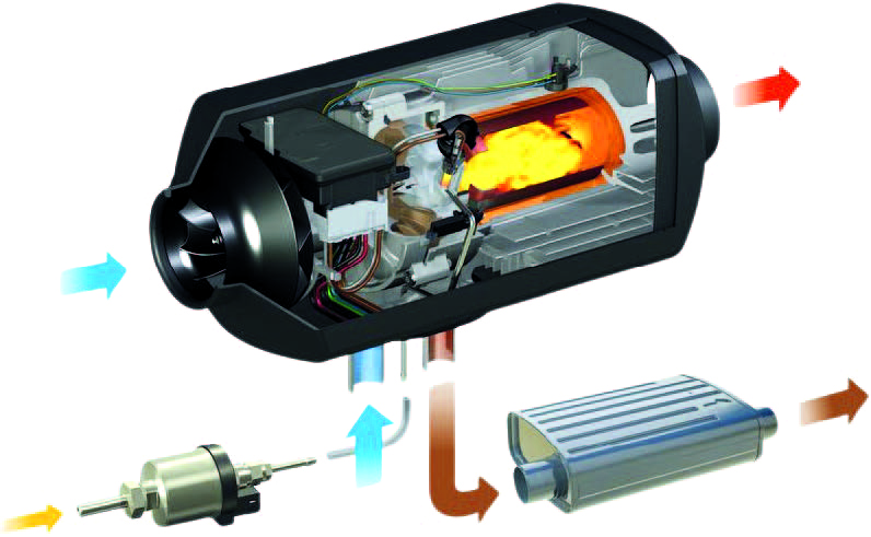
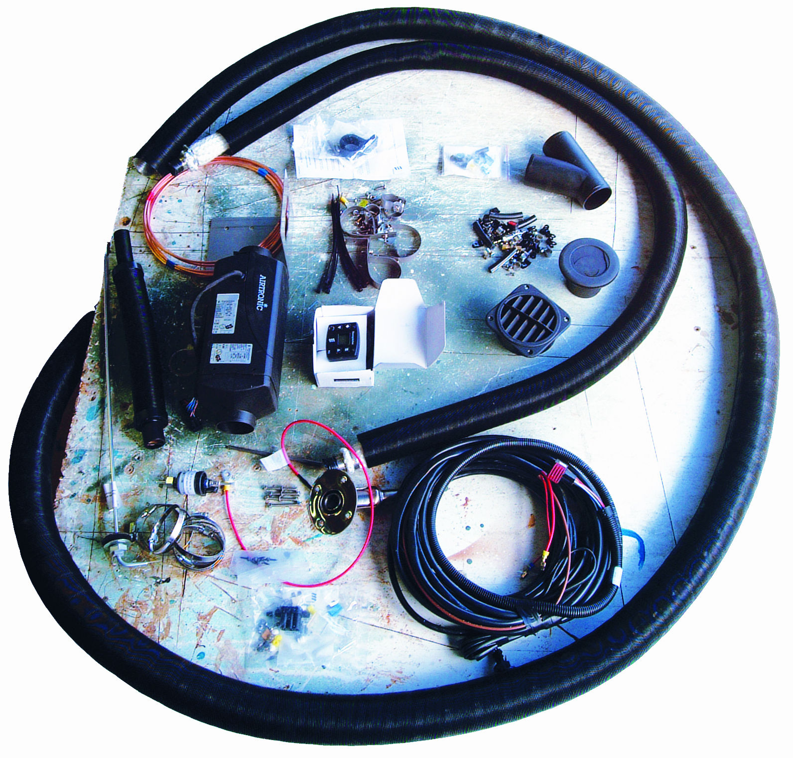
I’ve installed and used various hot air heaters over the years, and the one thing that always impresses me is how much easier each successive unit has been to install. This latest Airtronic D2 is certainly maintaining the tradition with its pre-wired cable loom, which means the only ‘bare ends’ connection is the positive and negative to the fuseboard and earth busbar. So, if you are contemplating a DIY installation and have the skills to maintain your own vessel, this installation will be a doddle!
Exhaust installation
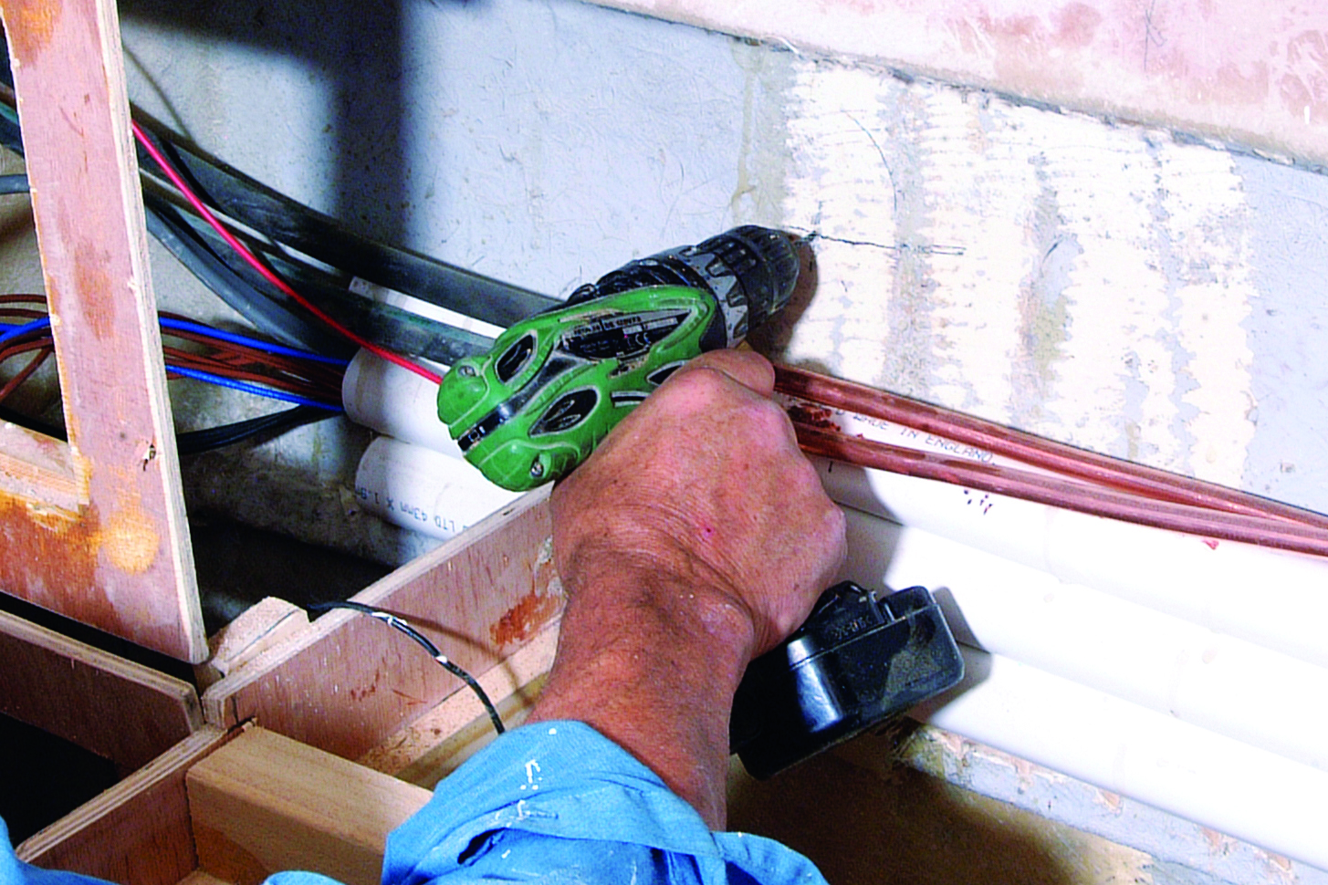
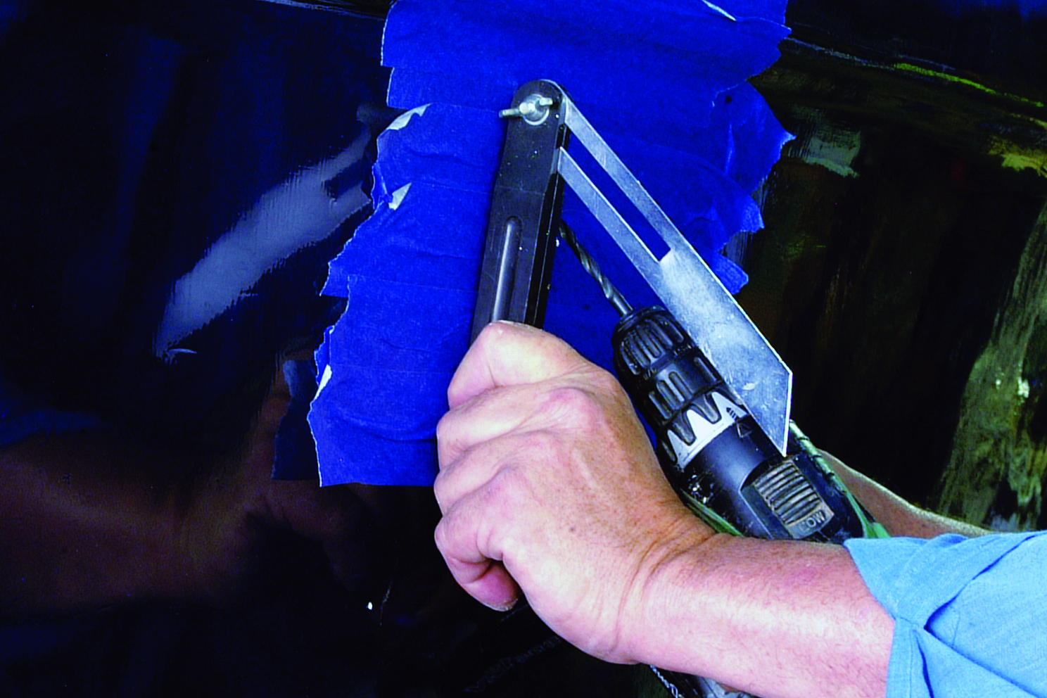
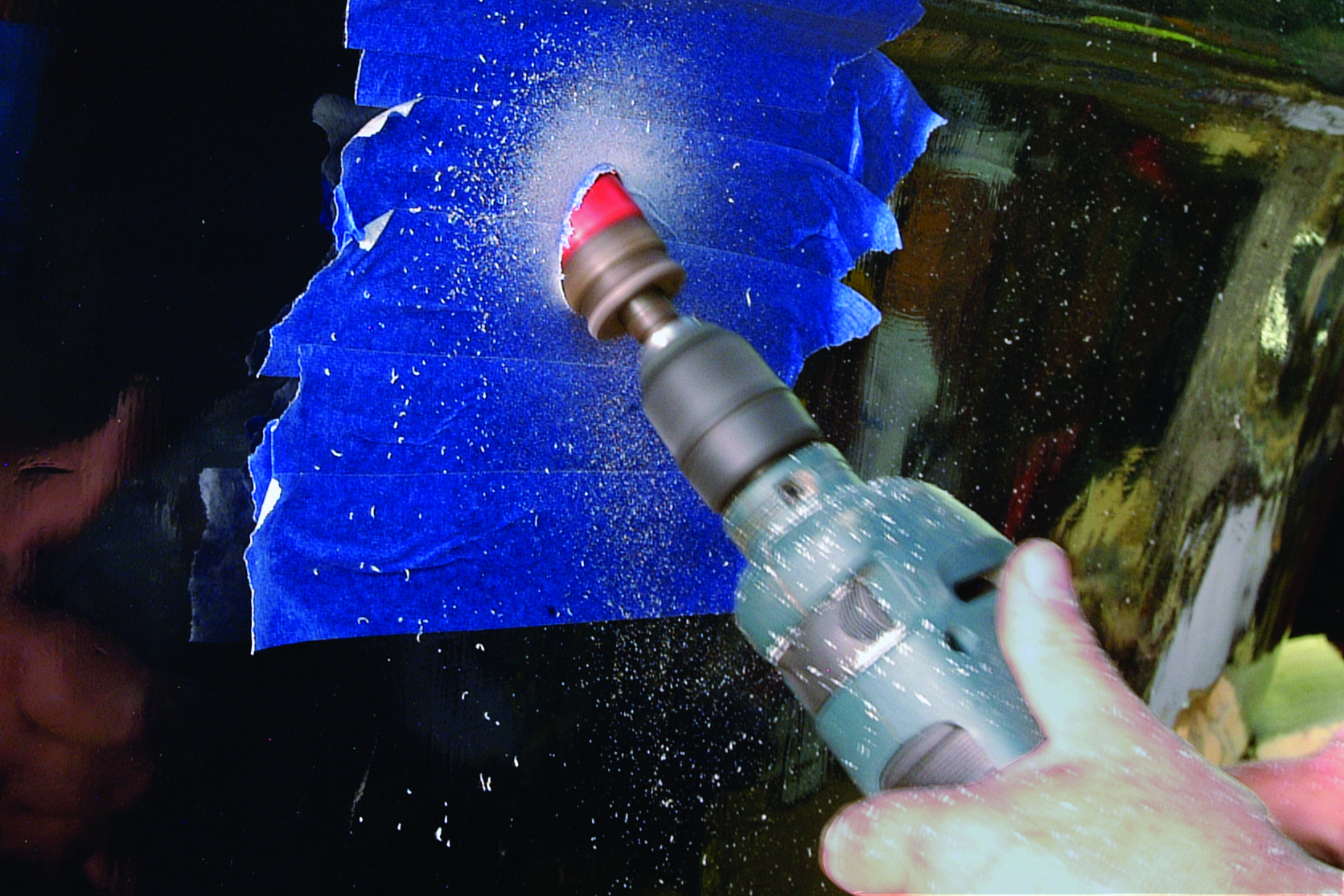
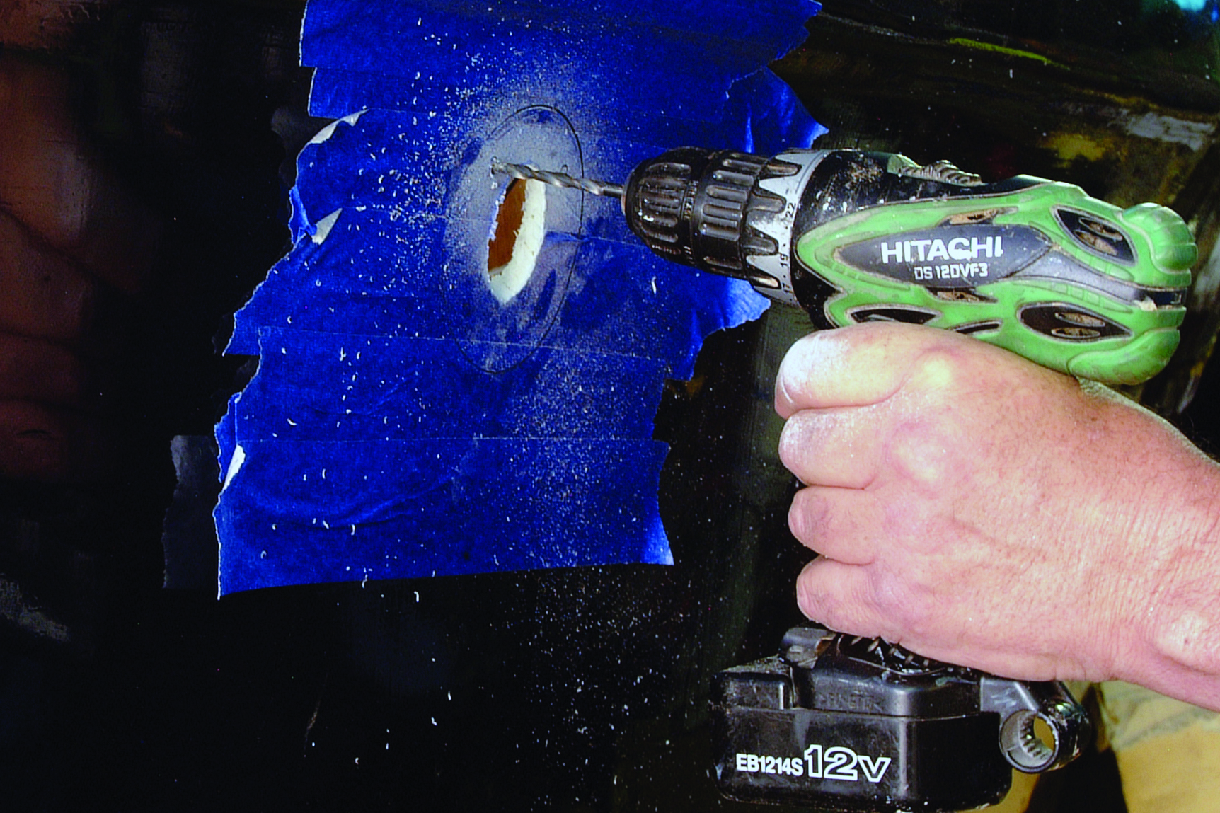
Our first job was to install the exhaust outlet, beginning by marking its position on the inside of the hull. First a small pilot hole was drilled through to indicate the position of the fitting on the inside of the hull to ensure there was nothing to get in the way. The working area was protected with masking tape. Using an angle finder set to the angle of the exhaust fitting, the pilot hole was re-drilled at the appropriate angle using a drill bit of the correct size to accept the guide rod included in the kit.
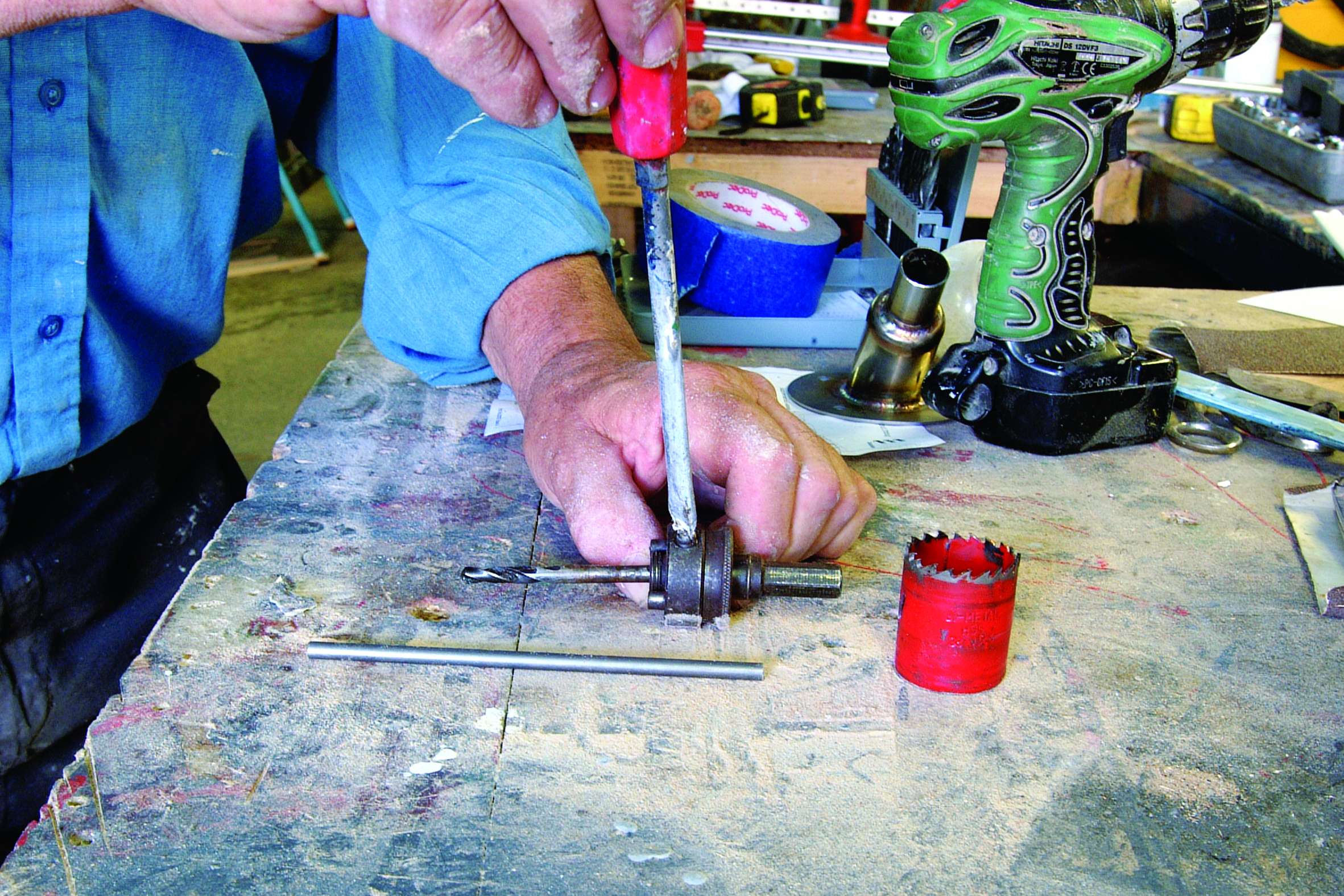
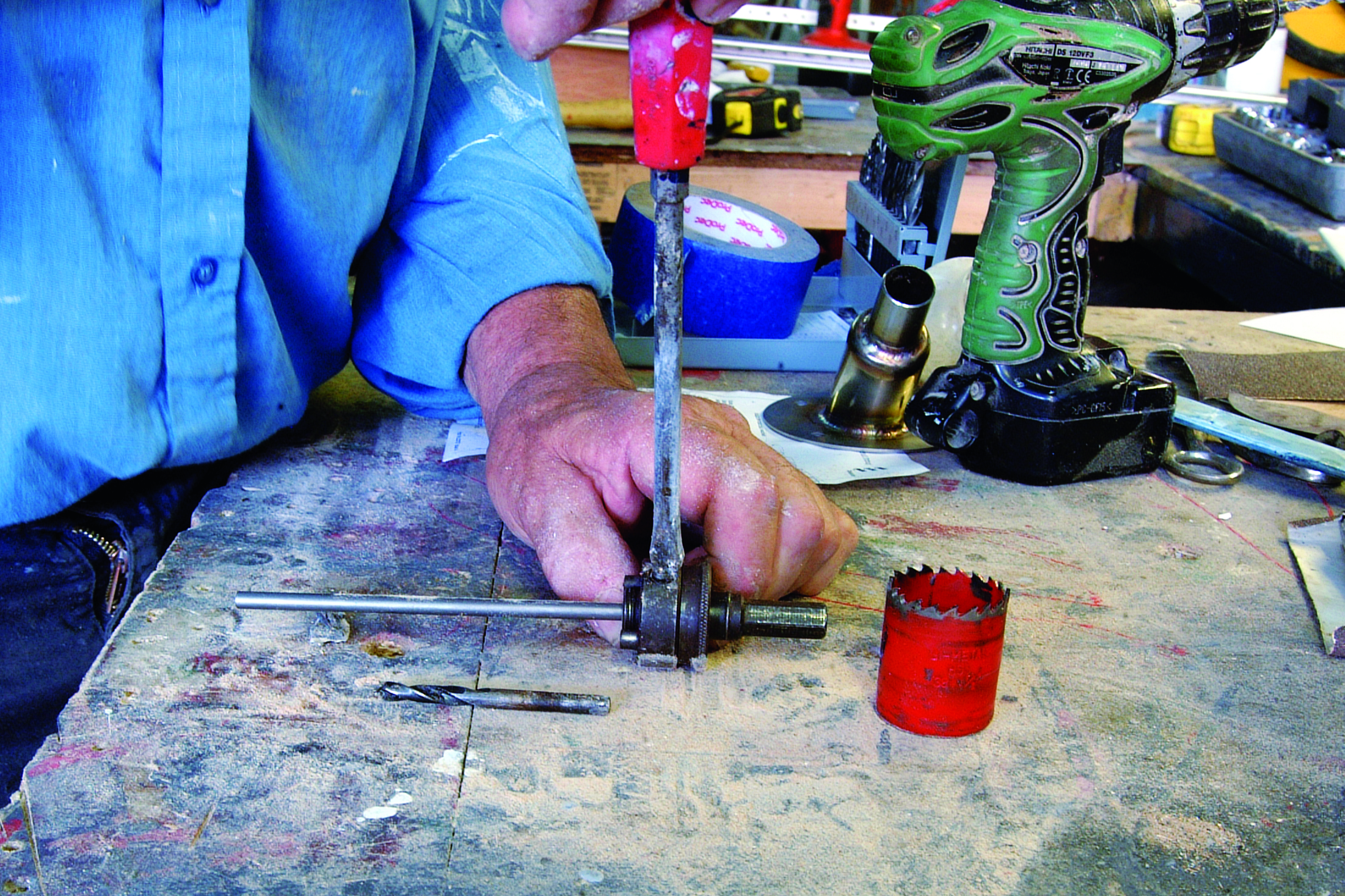
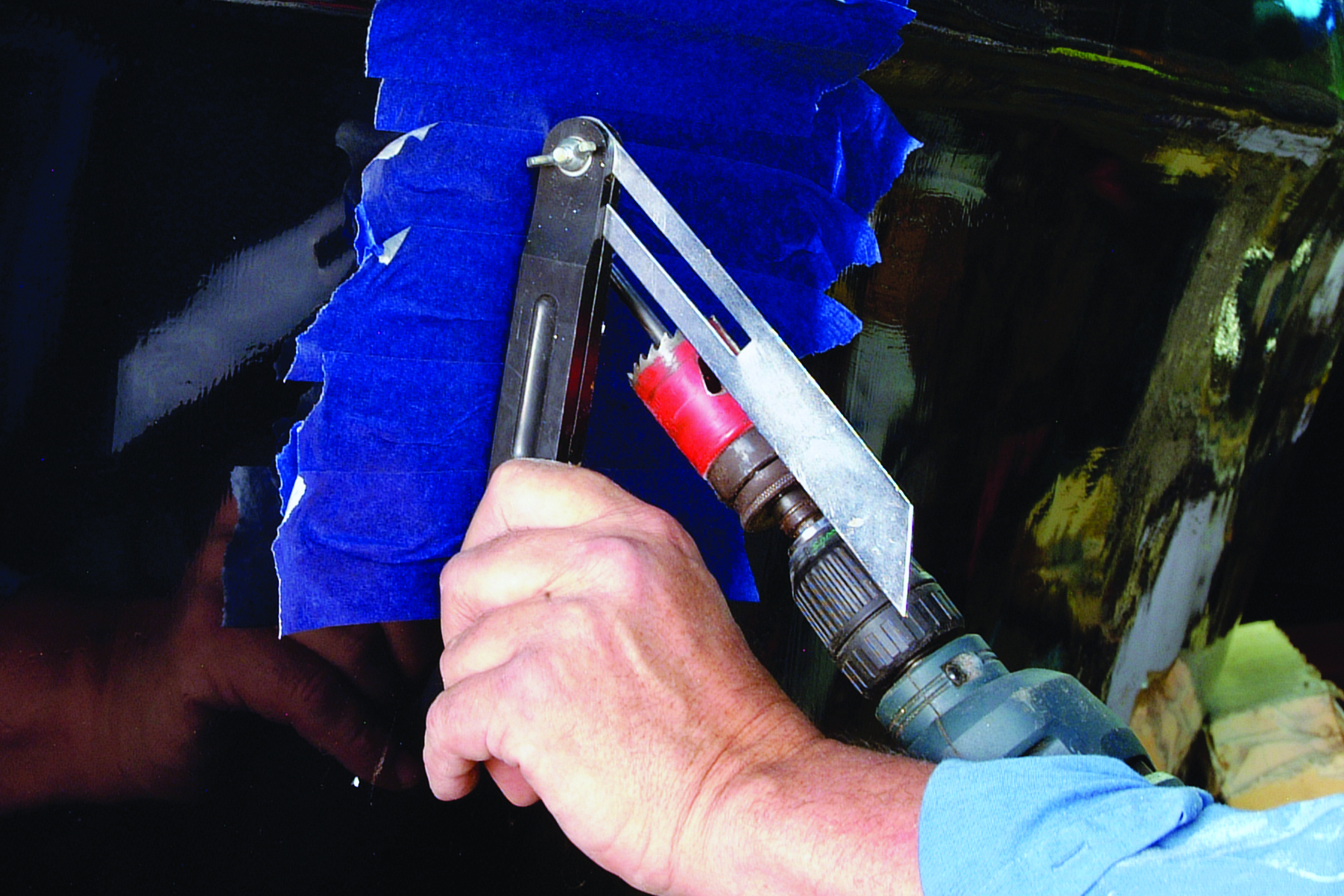
The pilot bit was removed from the hole saw arbour and replaced with the guide rod. A hole saw of the appropriate size to suit the exhaust fitting was fitted to the arbour, and again using the angle finder to double-check the angle, the guide rod was inserted into the pilot hole. The hole was then completed at the correct angle to suit the fitting.
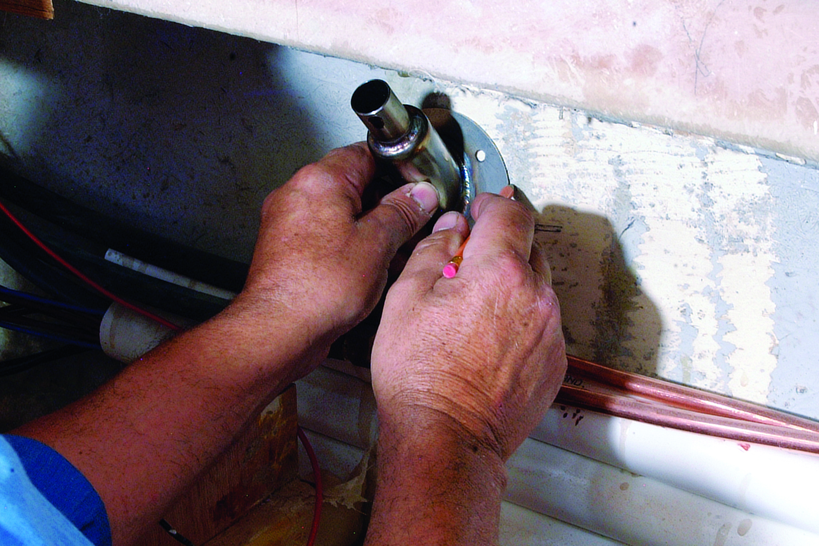
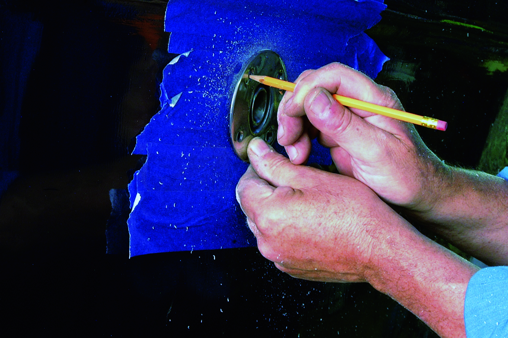
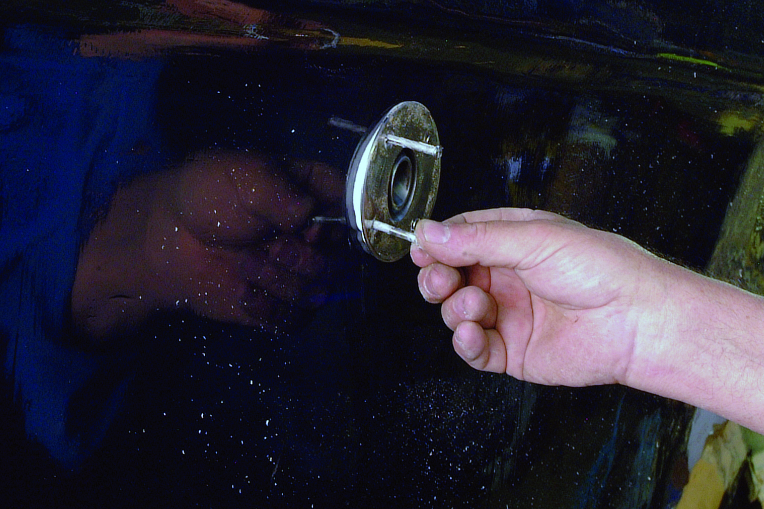
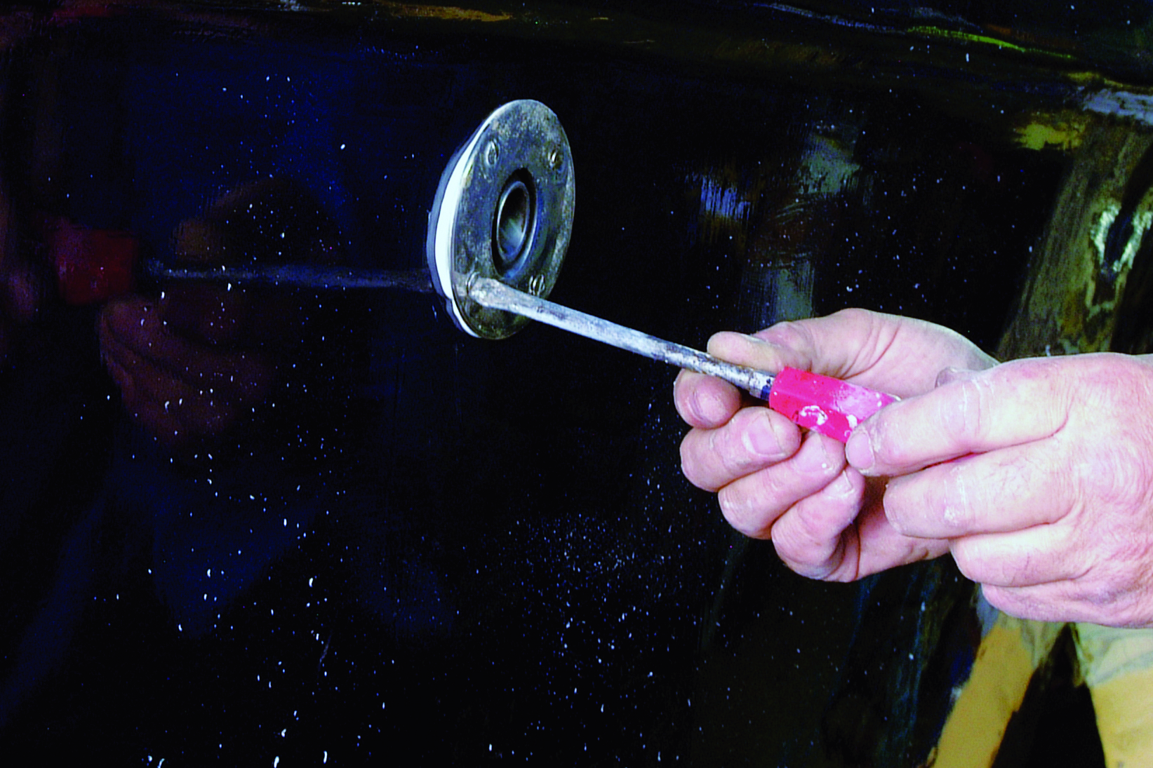
The fitting was offered up and checked to ensure the flange fitted flush against the hull. The holes for the securing bolts were then marked onto the masking tape.

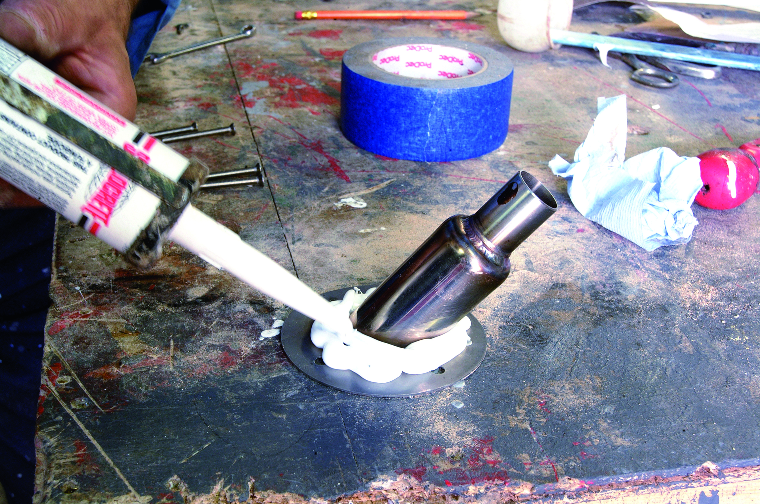
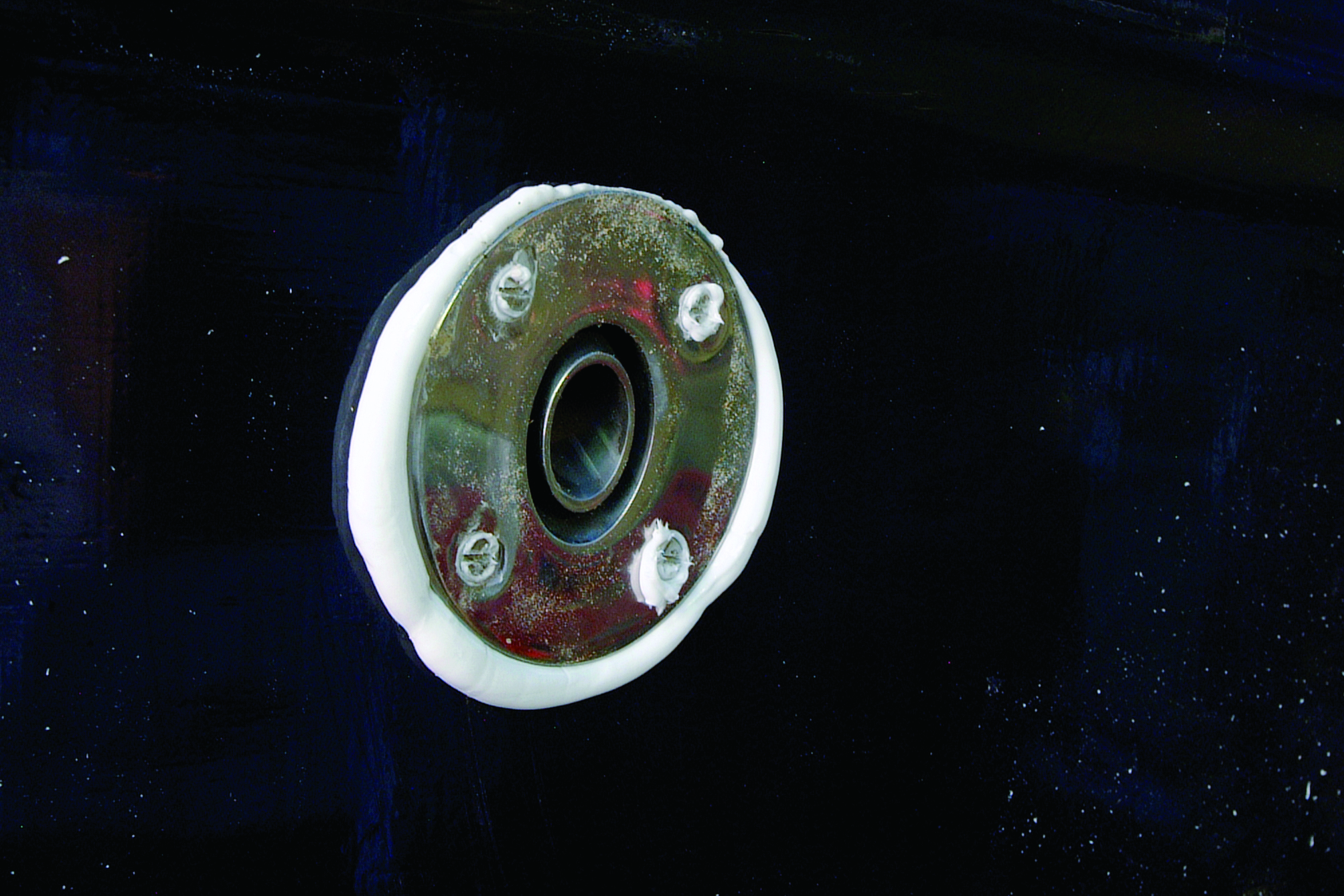
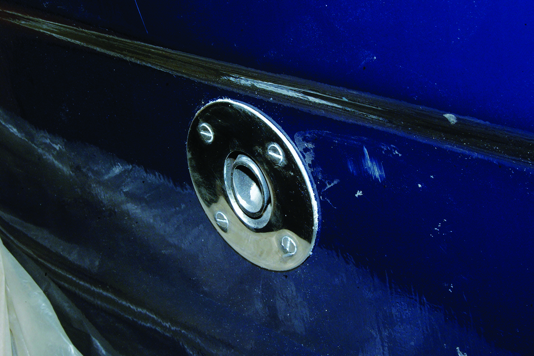
Next, the holes were drilled, ready to accept the bolts. Silicone sealant was applied to the flange of the exhaust fitting to ensure a watertight joint. The fitting was placed into position, and the securing bolts were inserted. The bolts were evenly tightened while a helper held the nuts inside and finally nipped them up. The excess silicone, which had squeezed out around the flange during the tightening process, was wiped off with a paper towel before it cured.
Heater and wiring loom installation
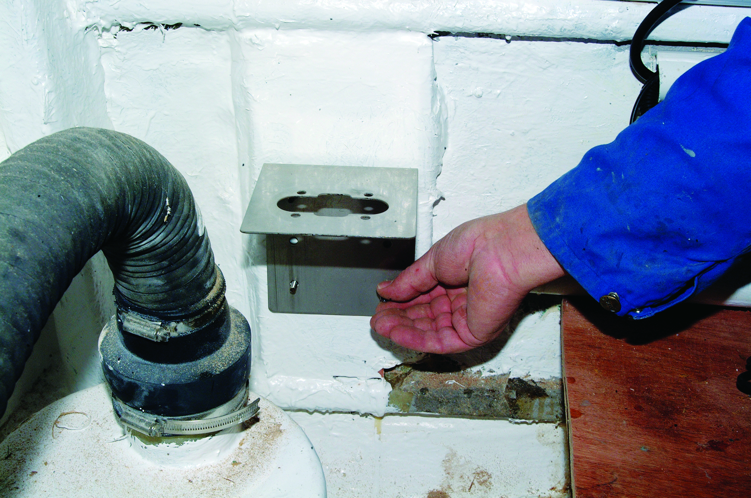
The first step here was to bond-in a timber base for the mounting bracket to be bolted onto. Nuts and bolts were threaded through the base prior to it being bonded to the hull, with the threads protected with masking tape. The bracket was then bolted onto the base. (The bracket can also be fitted the other way up if space is at a premium).
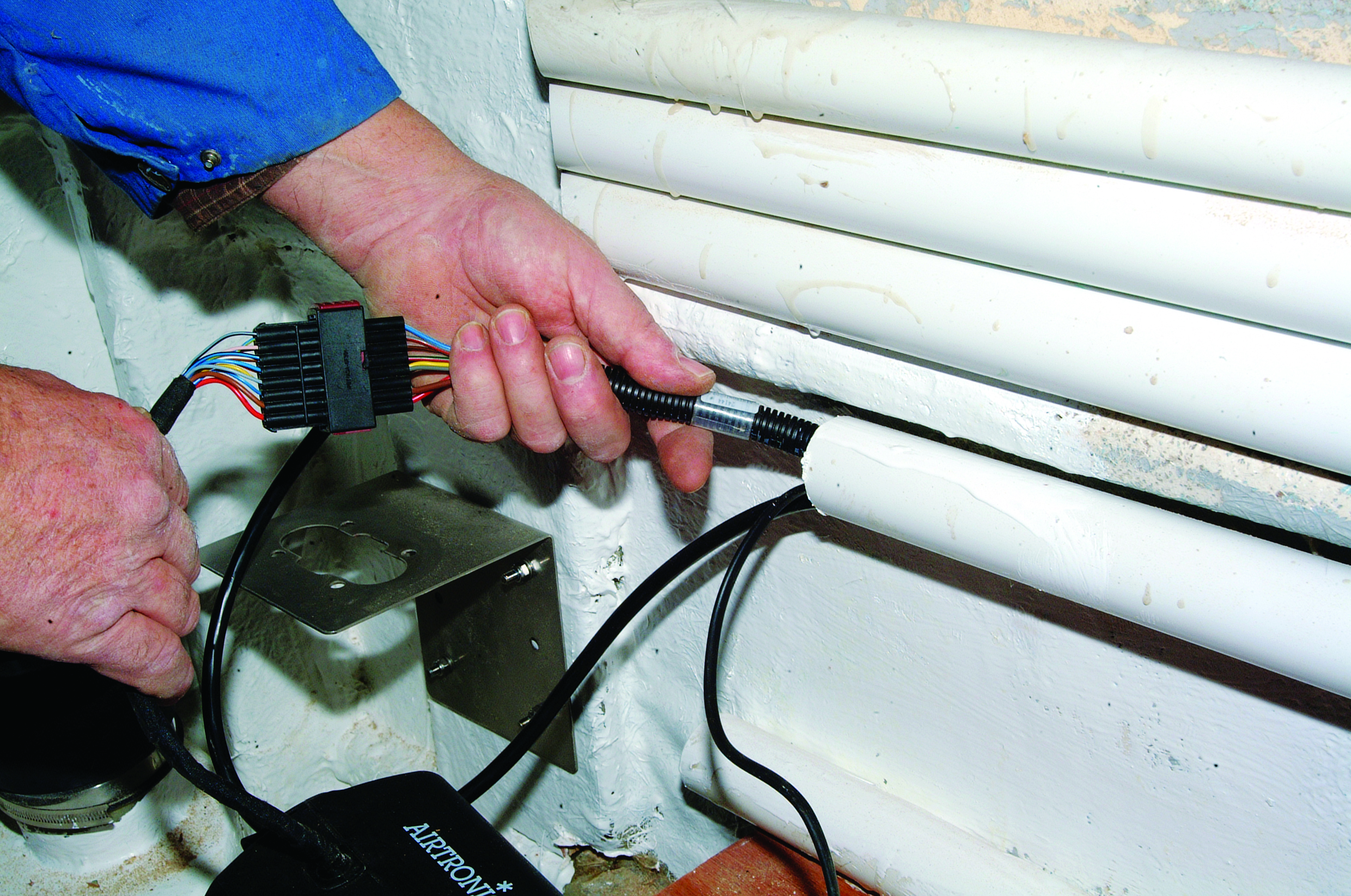
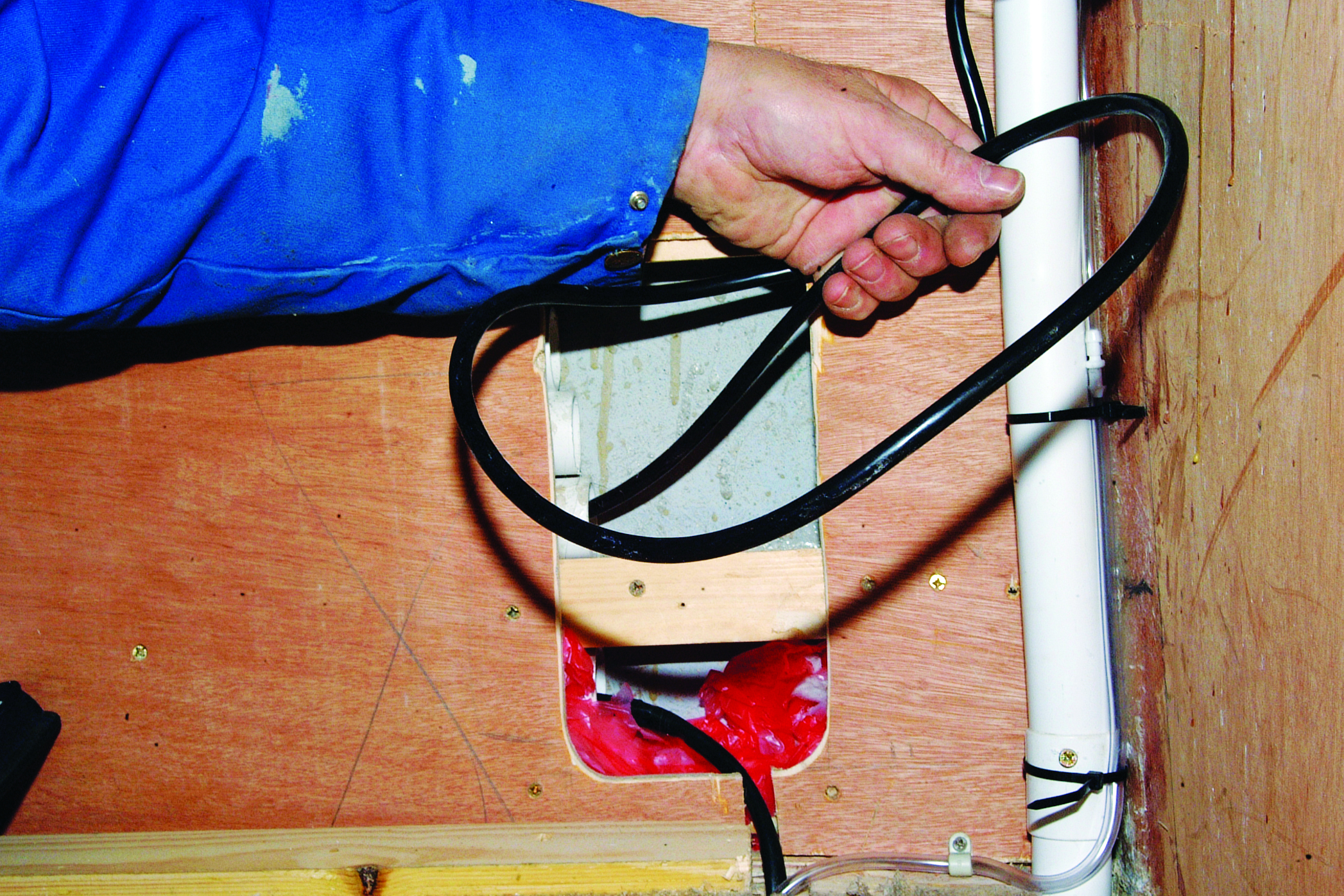
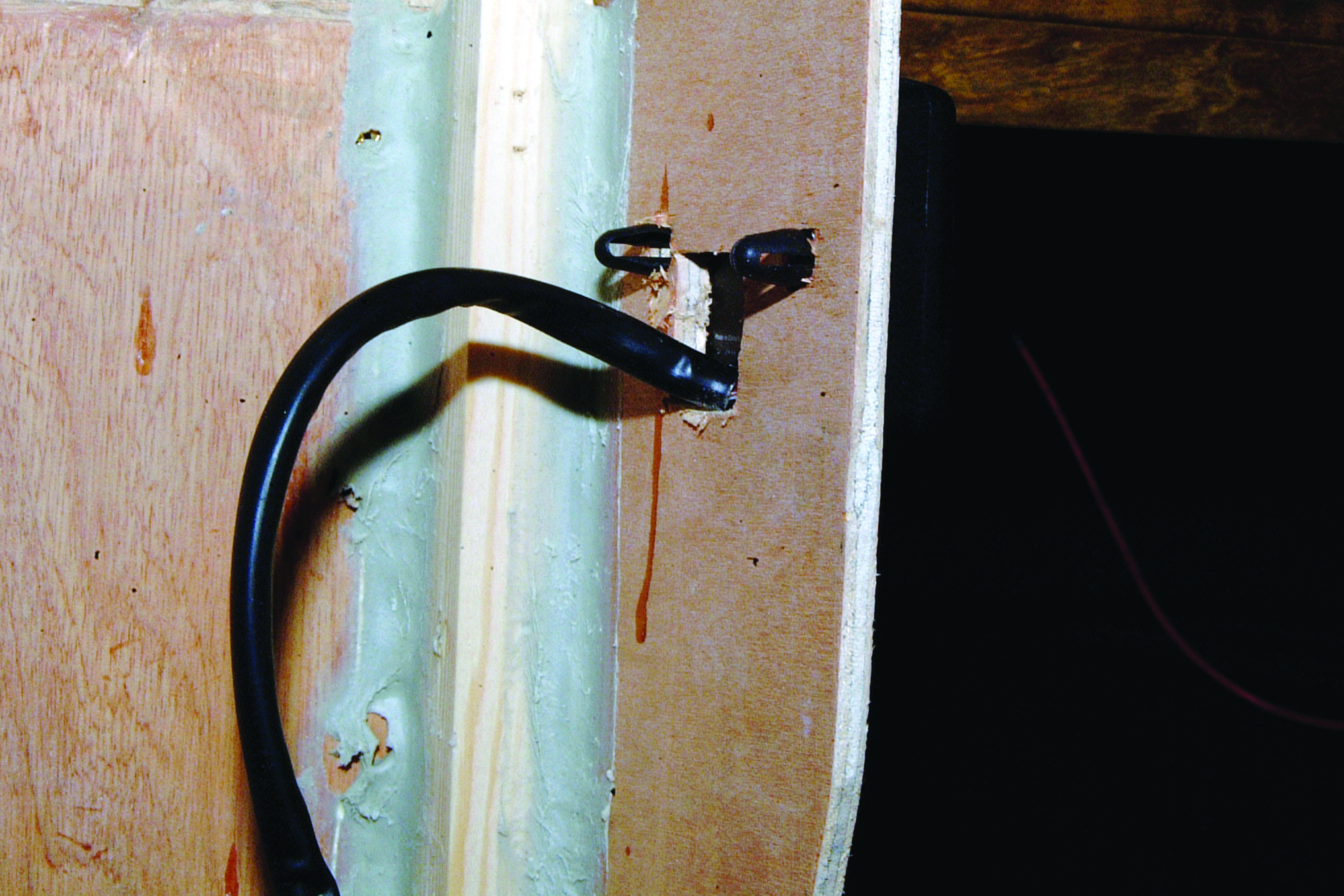
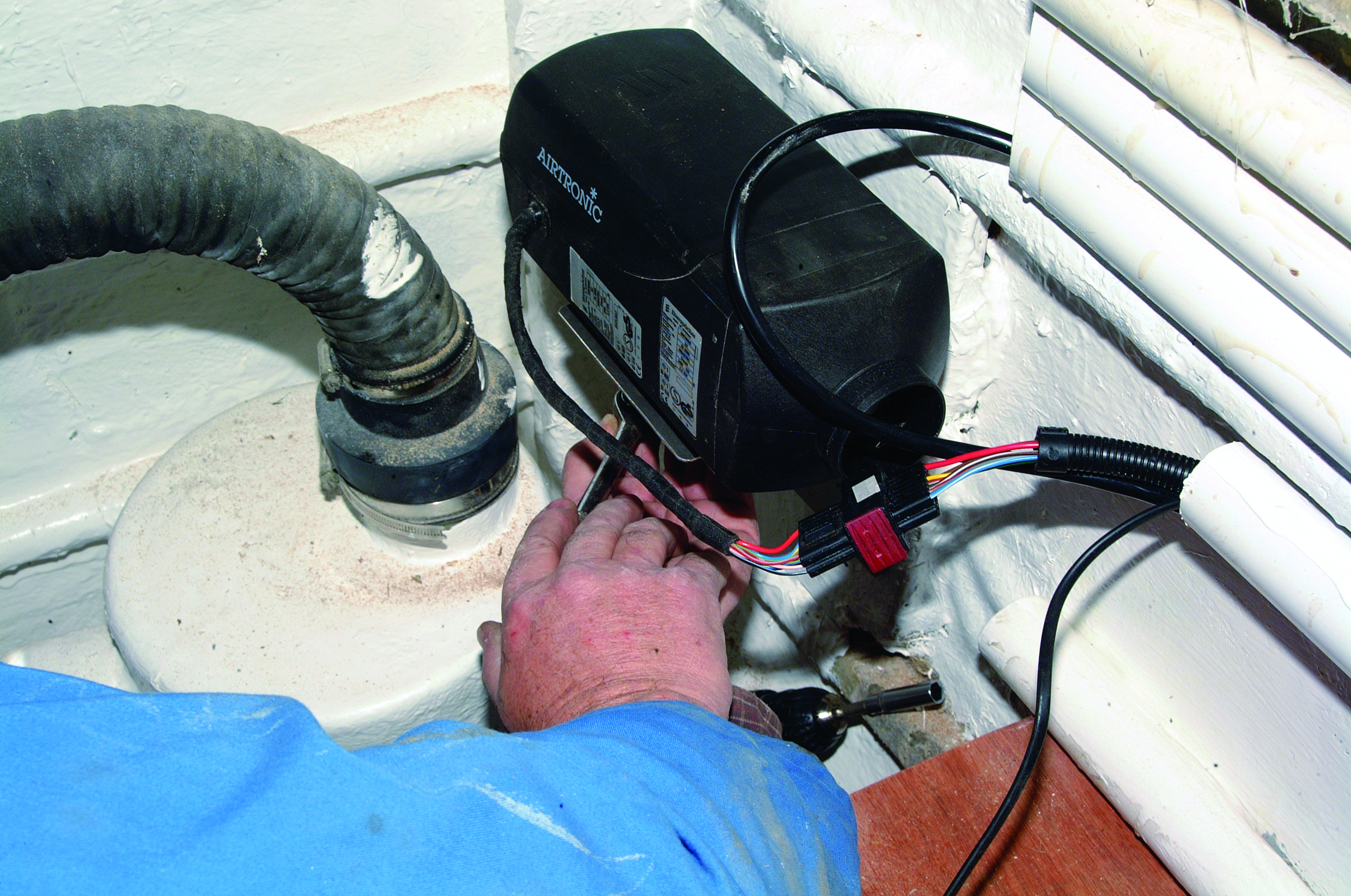
The next task was to pass the cable loom through the ducting running along the inside of the hull. Obviously, the majority of boats will not be equipped with spare ducting, so you will have to find the best way through and then protect the cables with trunking. Once the cables appeared inside, they were pulled through, ready for connecting. This one is the thermostat/control cable. The cable emerging from the lower duct is the 12-volt power supply running to the fuseboard.
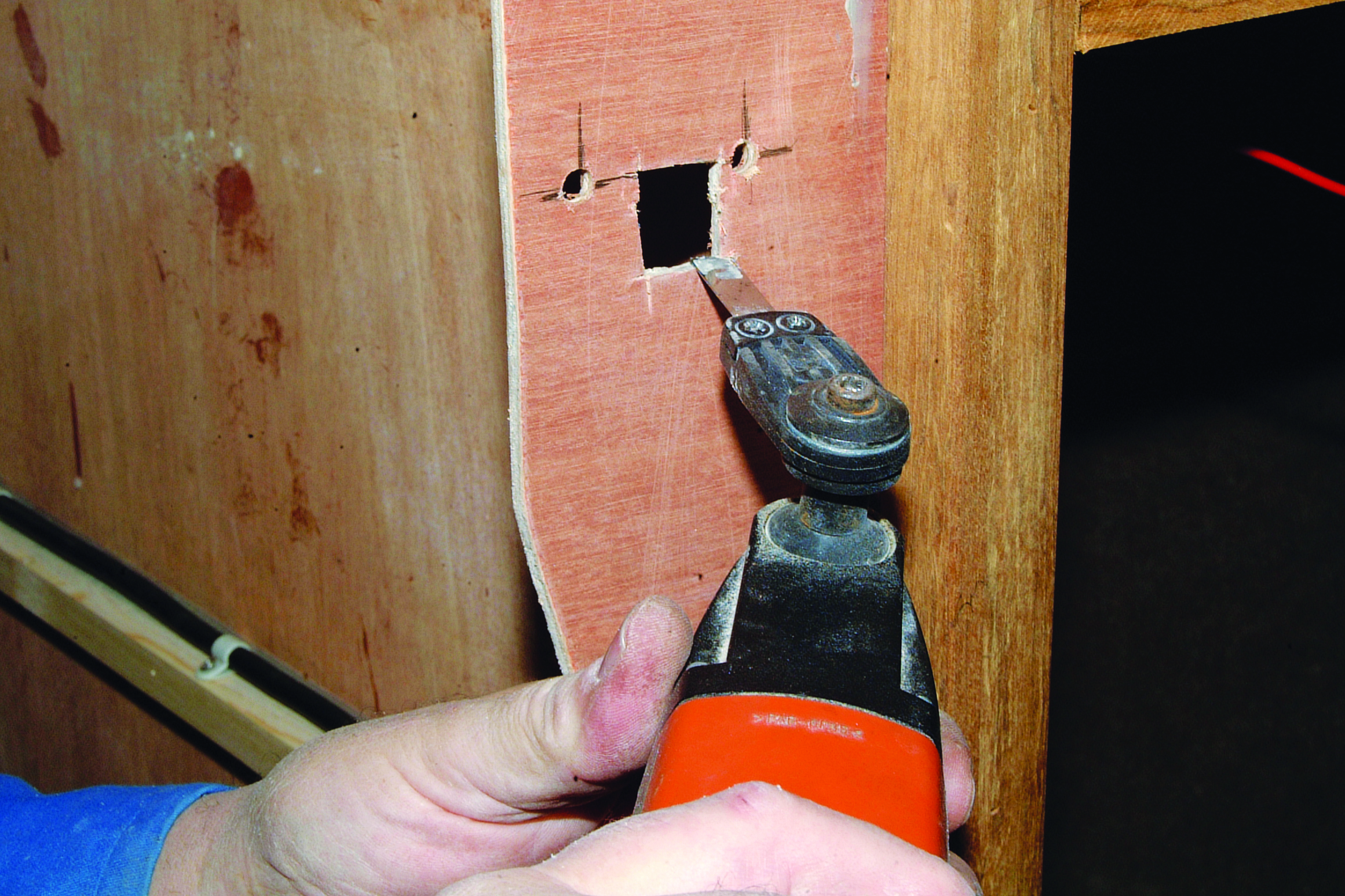
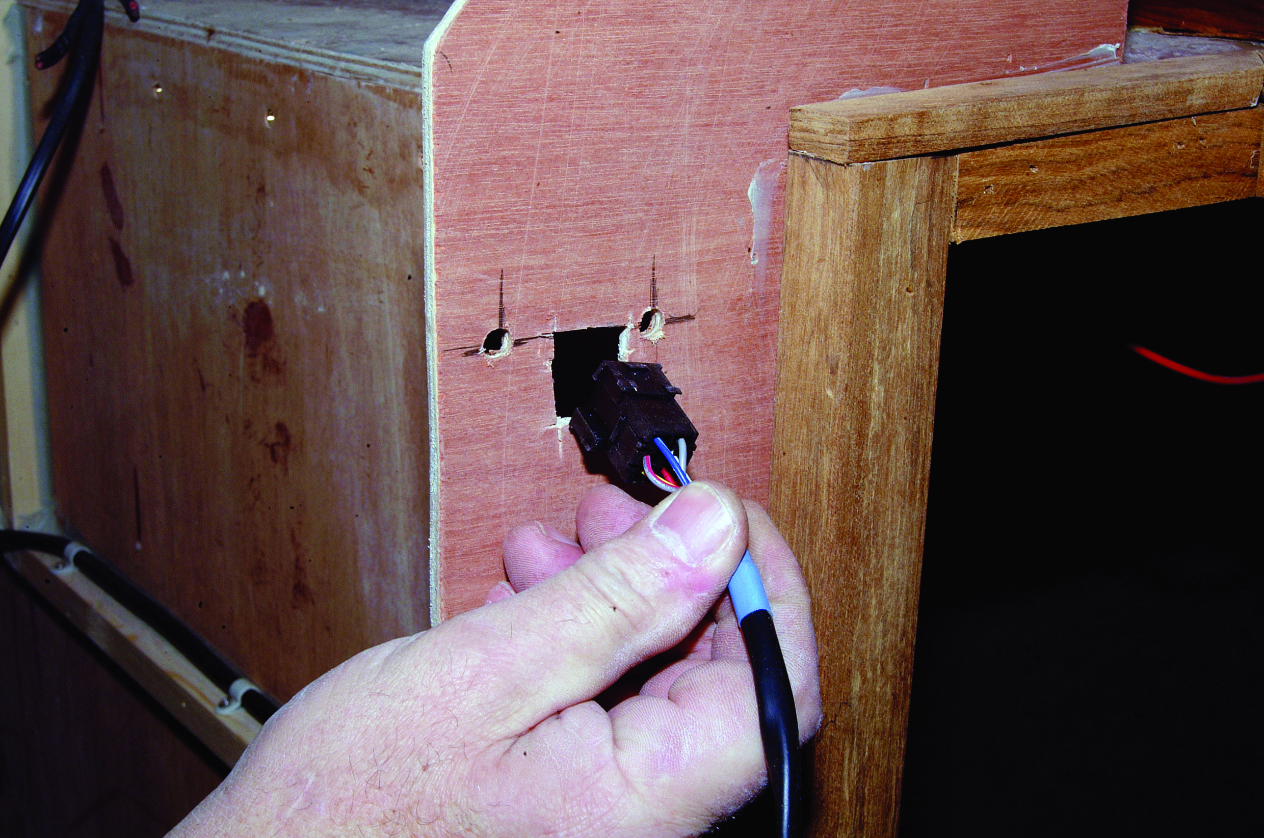
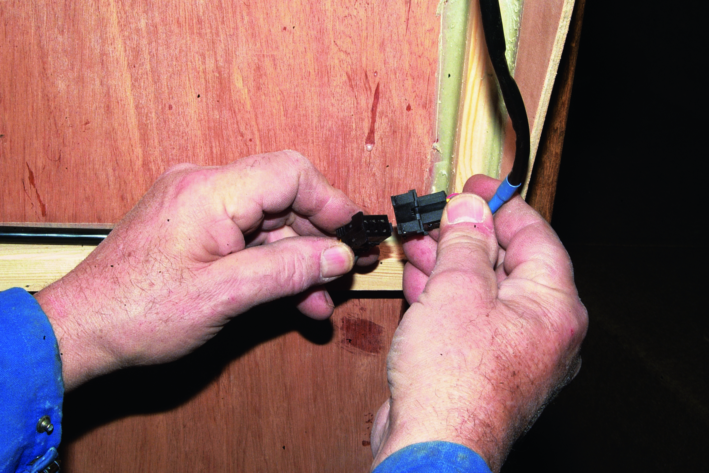
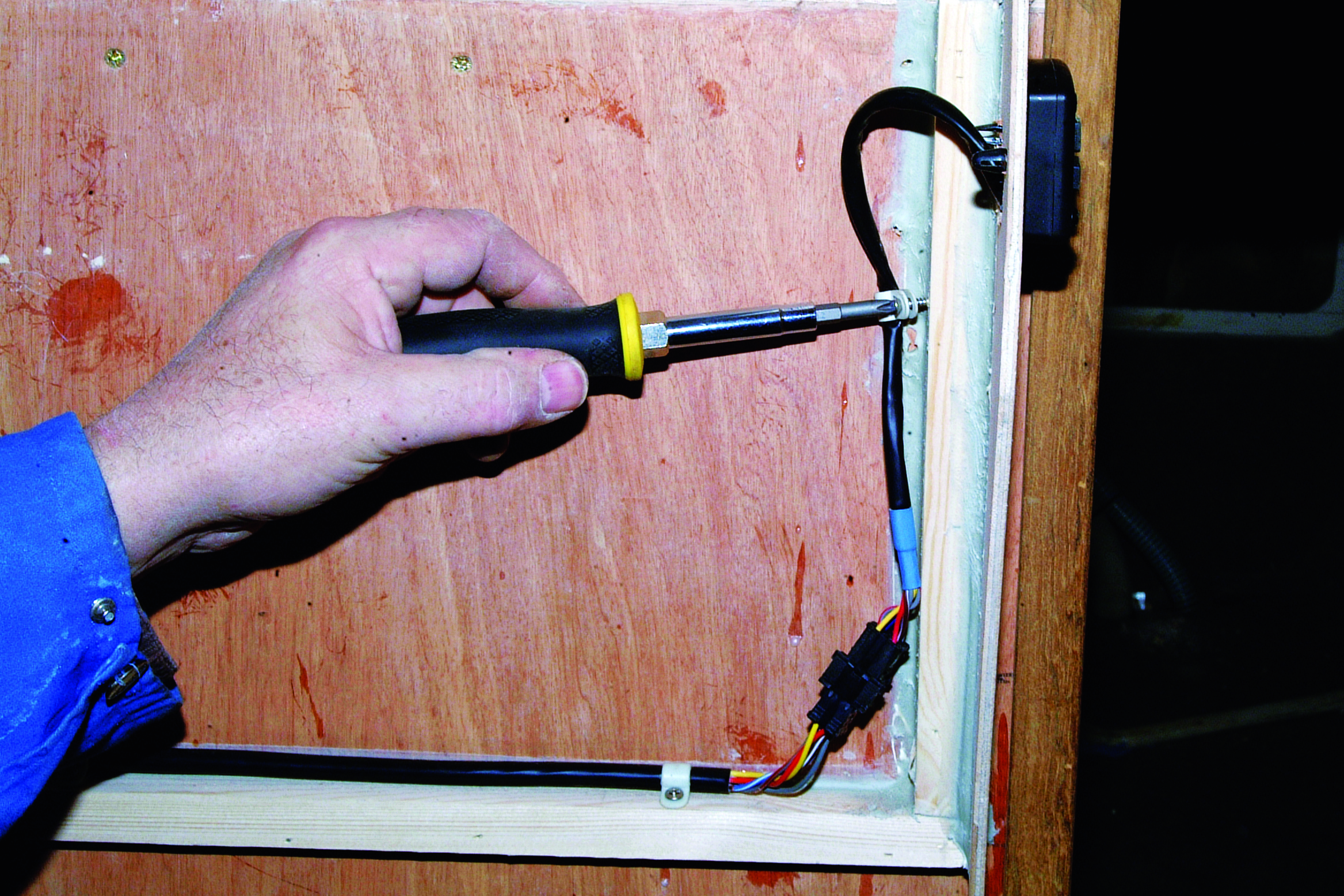
A multi-tool was used to cut out the aperture for the connector plug on the thermostat cable while the two holes for the fixing pegs were drilled. The plug could then be passed through the panel, followed by the cable. The fixing pegs compress as they are pushed through the panel and then expand to hold the thermostat firmly in position. The plug can then be connected to the socket on the loom. The cable was clipped into place behind the panel.
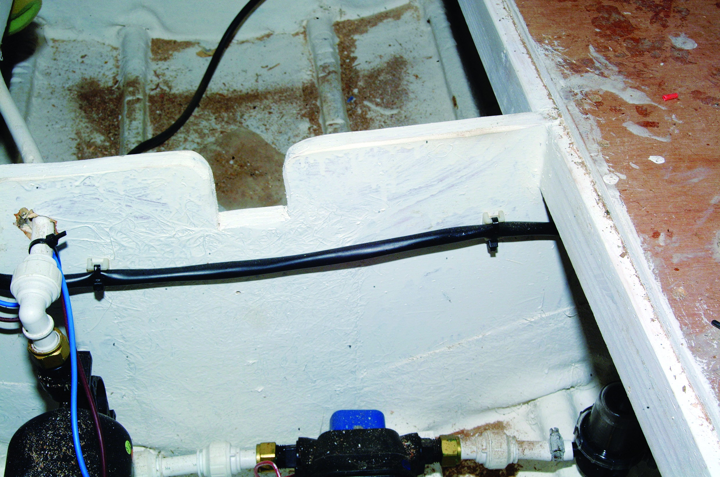
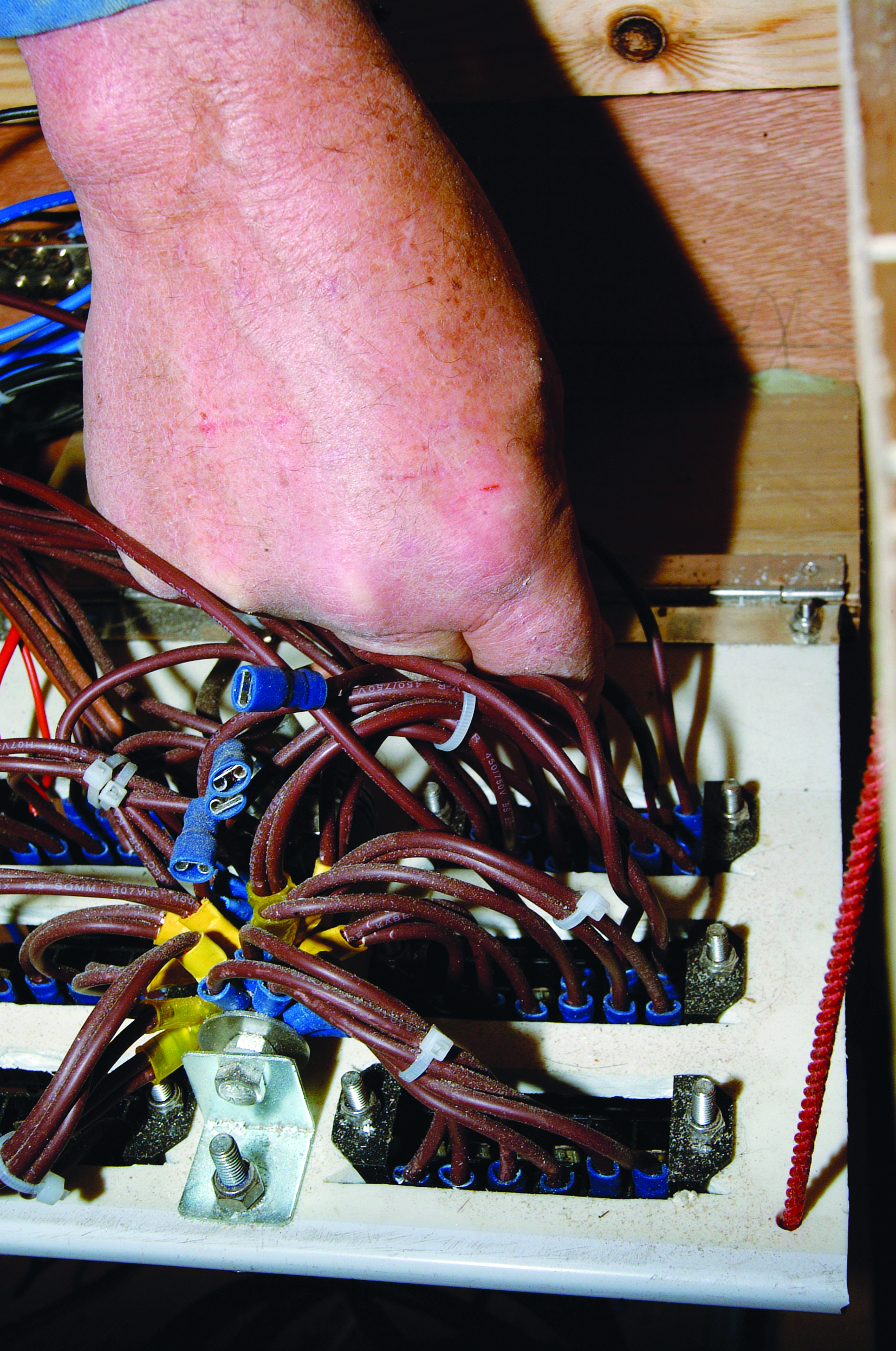
The 12-volt power cable was run through the bilge, where it was also clipped out of harm’s way. The cables were then terminated with crimp terminals and plugged onto the two fuse connections – one 5-amp actuation fuse and one 20-amp mains power fuse. (You need to check the switchboard circuit breakers can handle this amount of extra current. It’s probably better to install on a fresh circuit(s) – Ed)
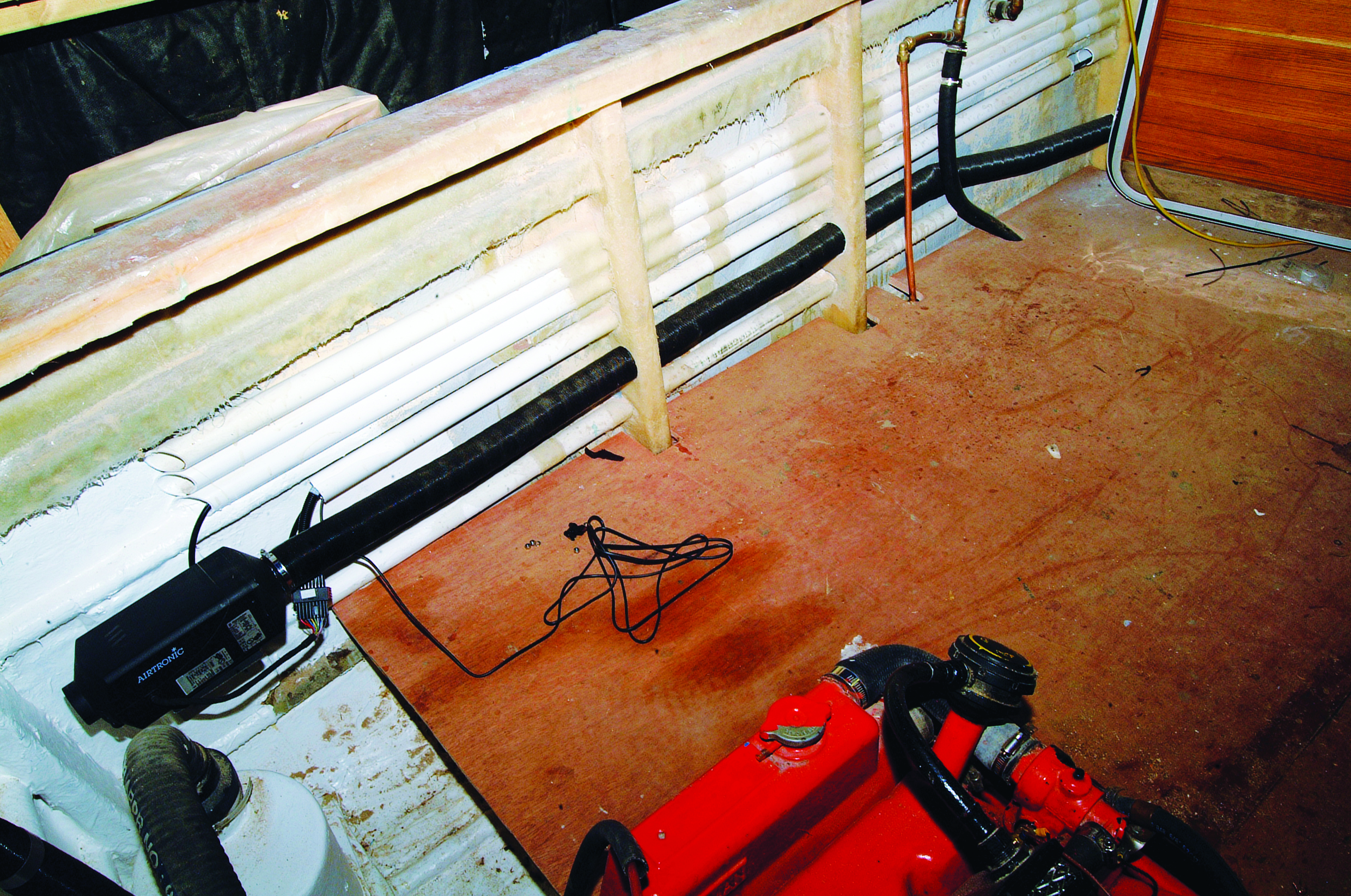
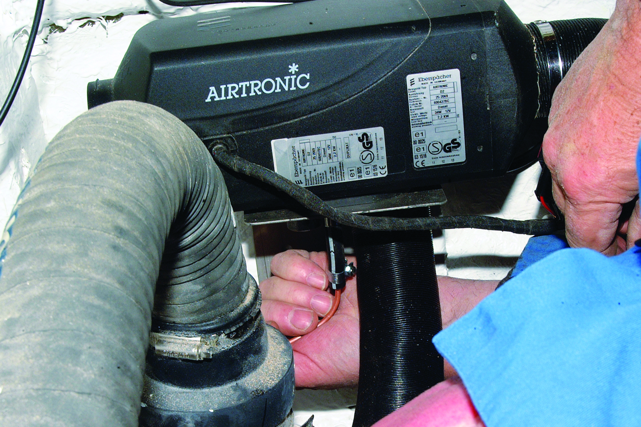
The heater unit could now be placed onto the mounting bracket and the nuts tightened onto the fixing studs.
Trunking installation
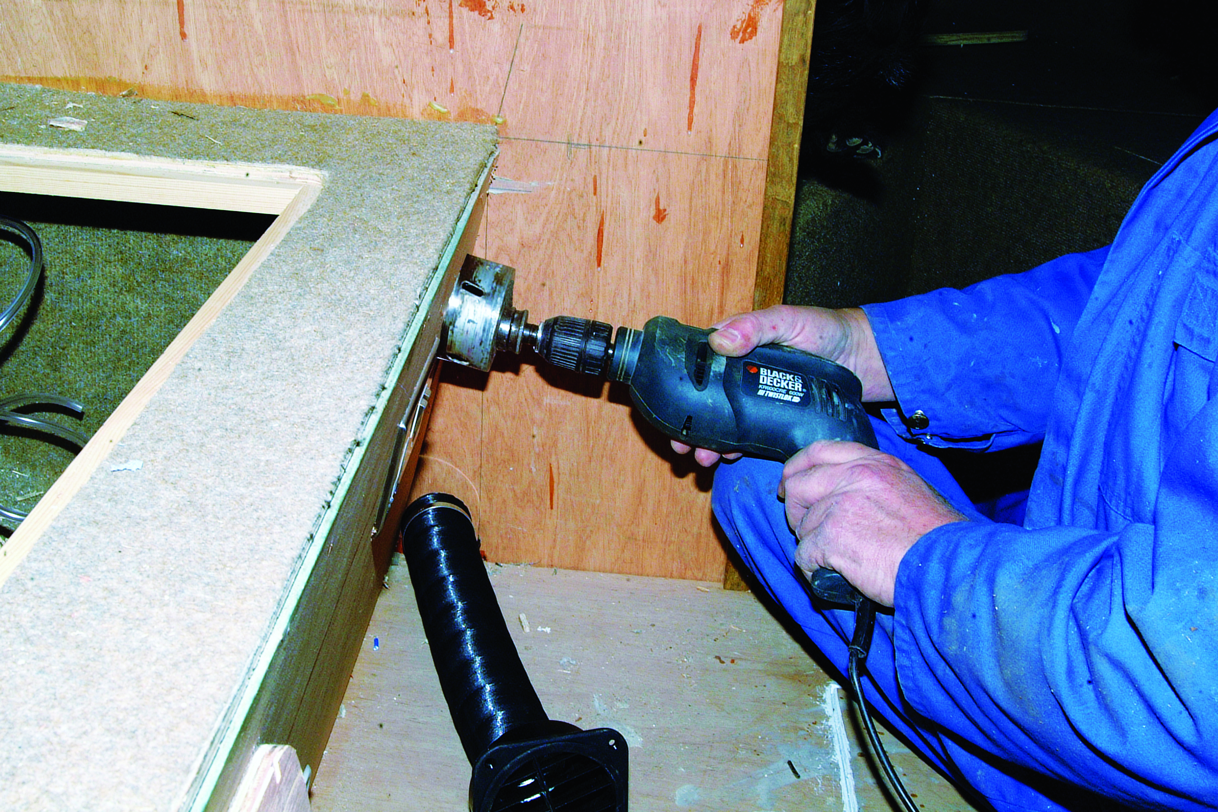
Both outlets of this system are being installed into the wheelhouse, as the fore-cabin is a very small area and will share the warm air. Using a hole saw slightly oversized for the outlet fittings (they don’t need to be a tight fit), the two outlet holes were cut in the front of the settee at each end to spread the flow of air.
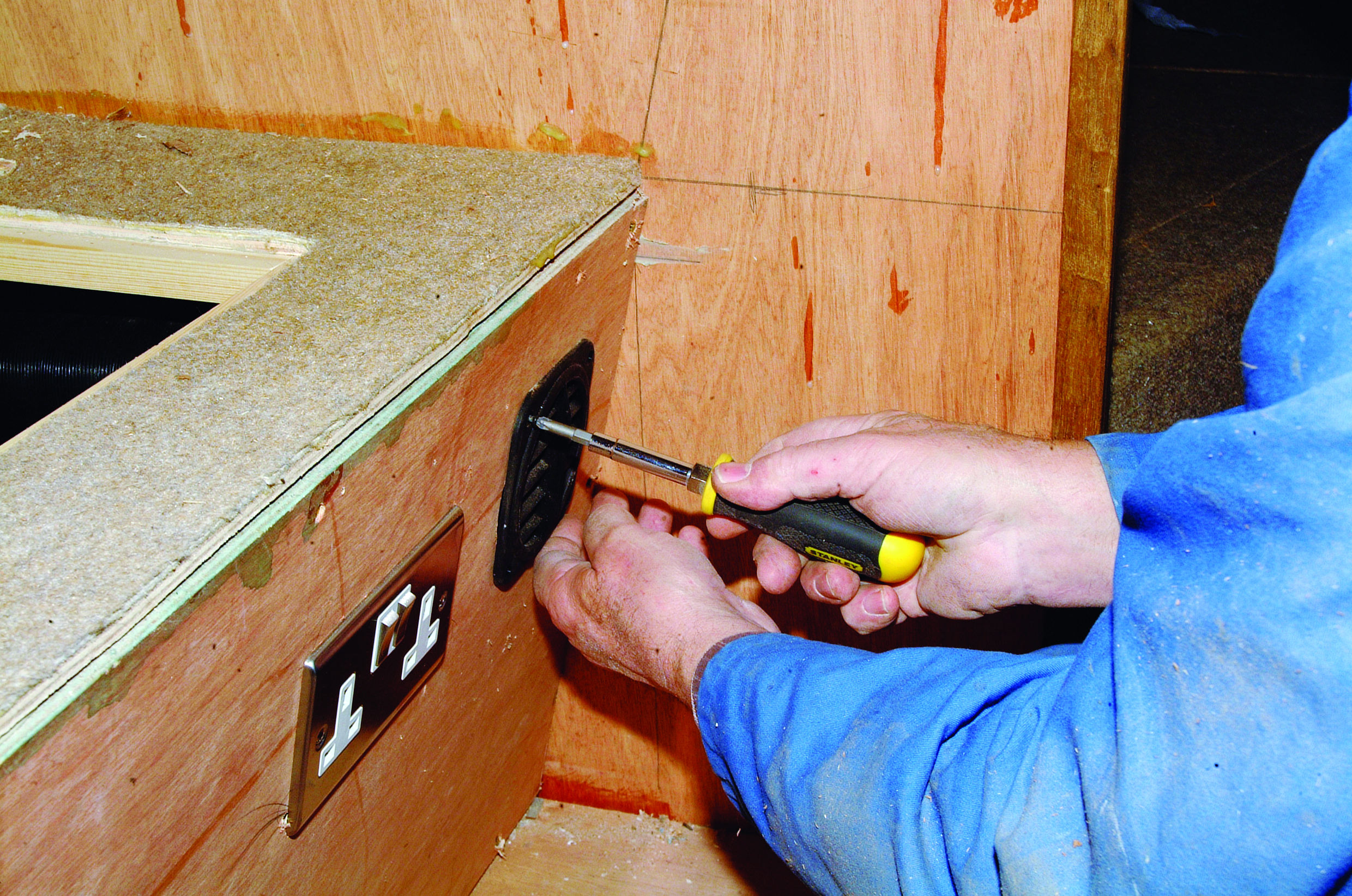
A length of trunking was cut to length, clipped to an outlet fitting, and the two were passed through one of the holes in the front of the settee. The outlet was then screwed into place on the front of the settee. The other outlet was similarly fitted, and both were attached to a ‘Y’ connector allowing warm air to flow to both outlets.
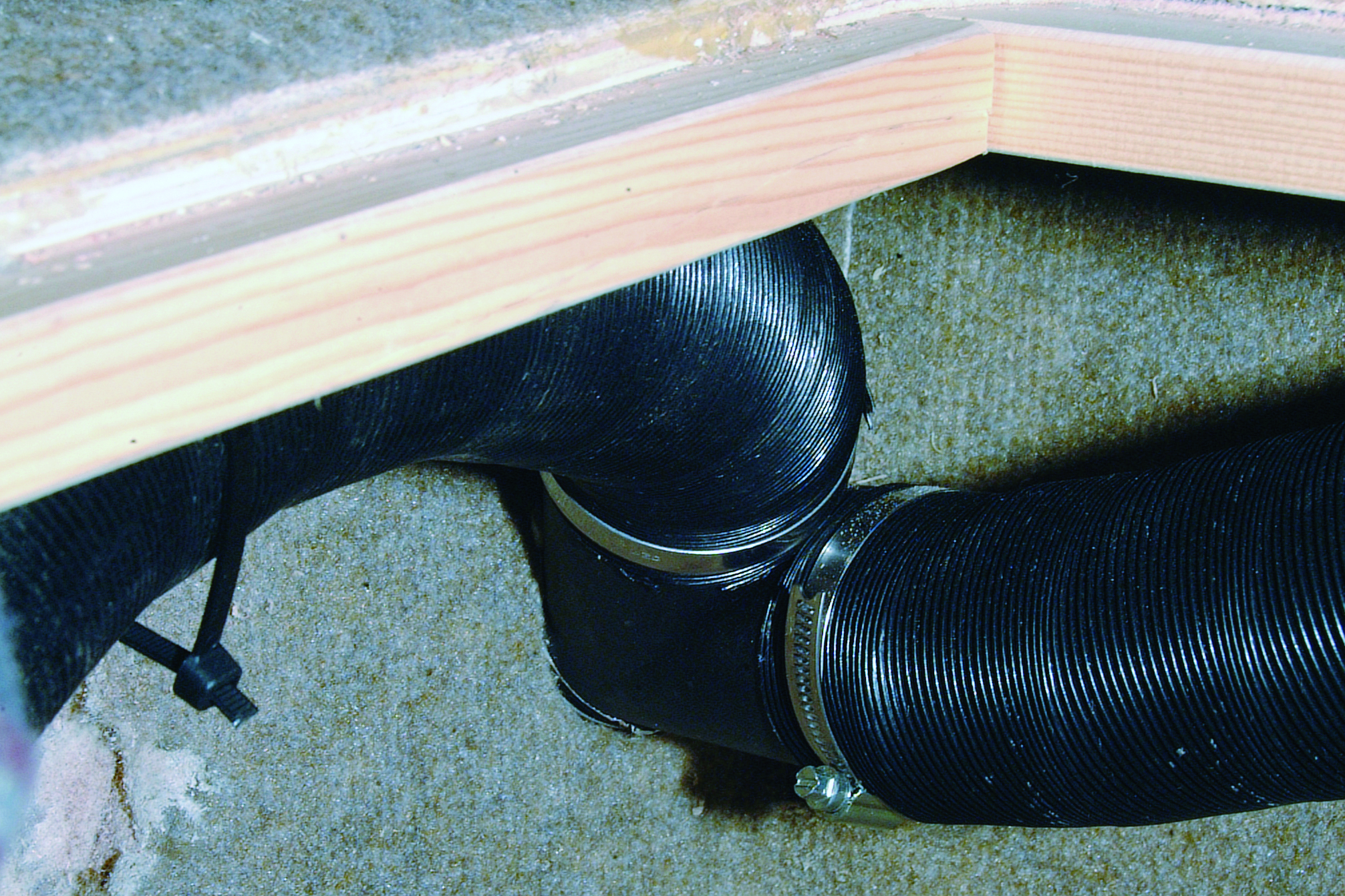
The trunking was run along the side of the hull up to the heater unit. As this was all pre-planned, it was an easy job, but you will need to find the most direct route that is also protected from damage to the trunking.
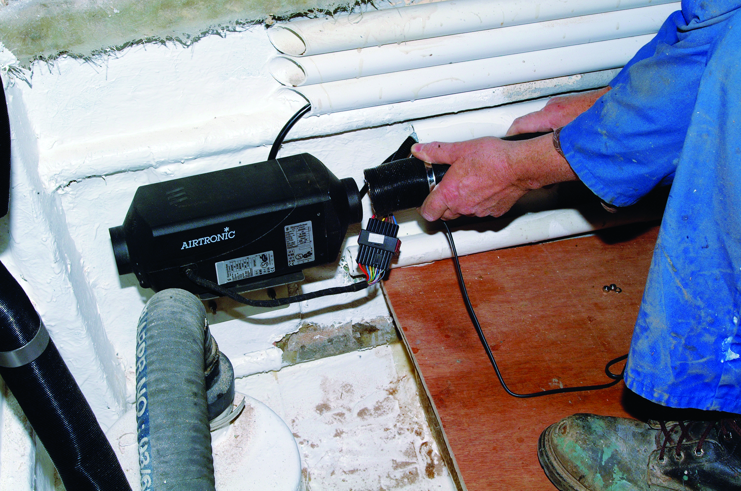
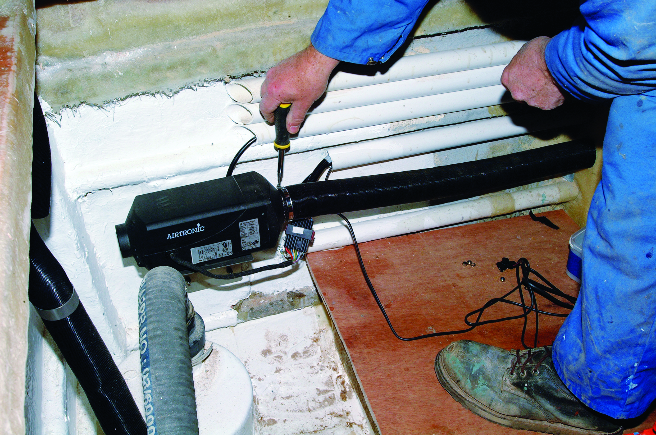
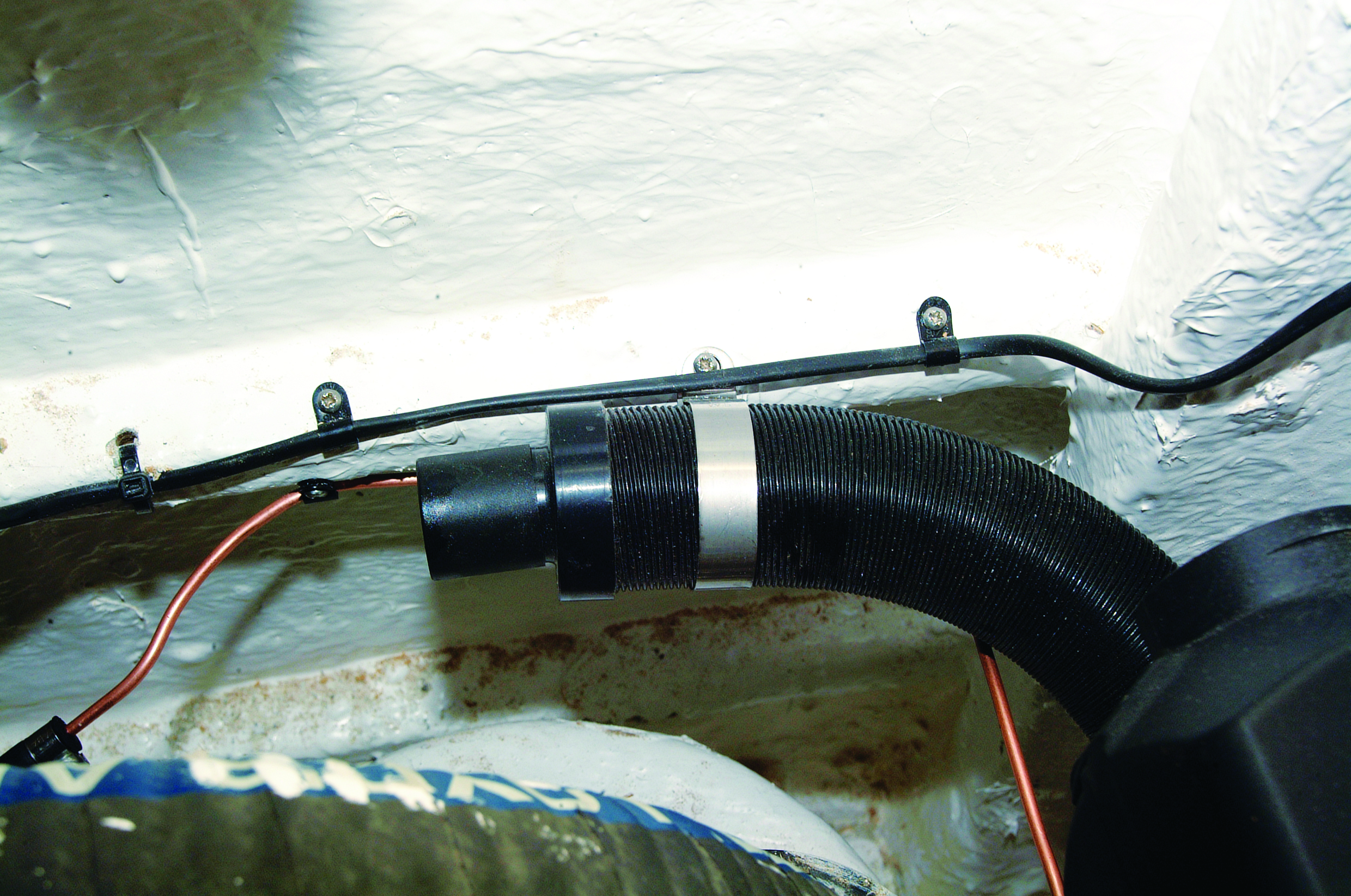
The trunking was clipped to the heater unit using one of the clips provided. I must admit this was a very easy installation, as the trunking ran alongside the cockpit, through the aft bulkhead, and into the accommodation.
Fuel system and pump installation
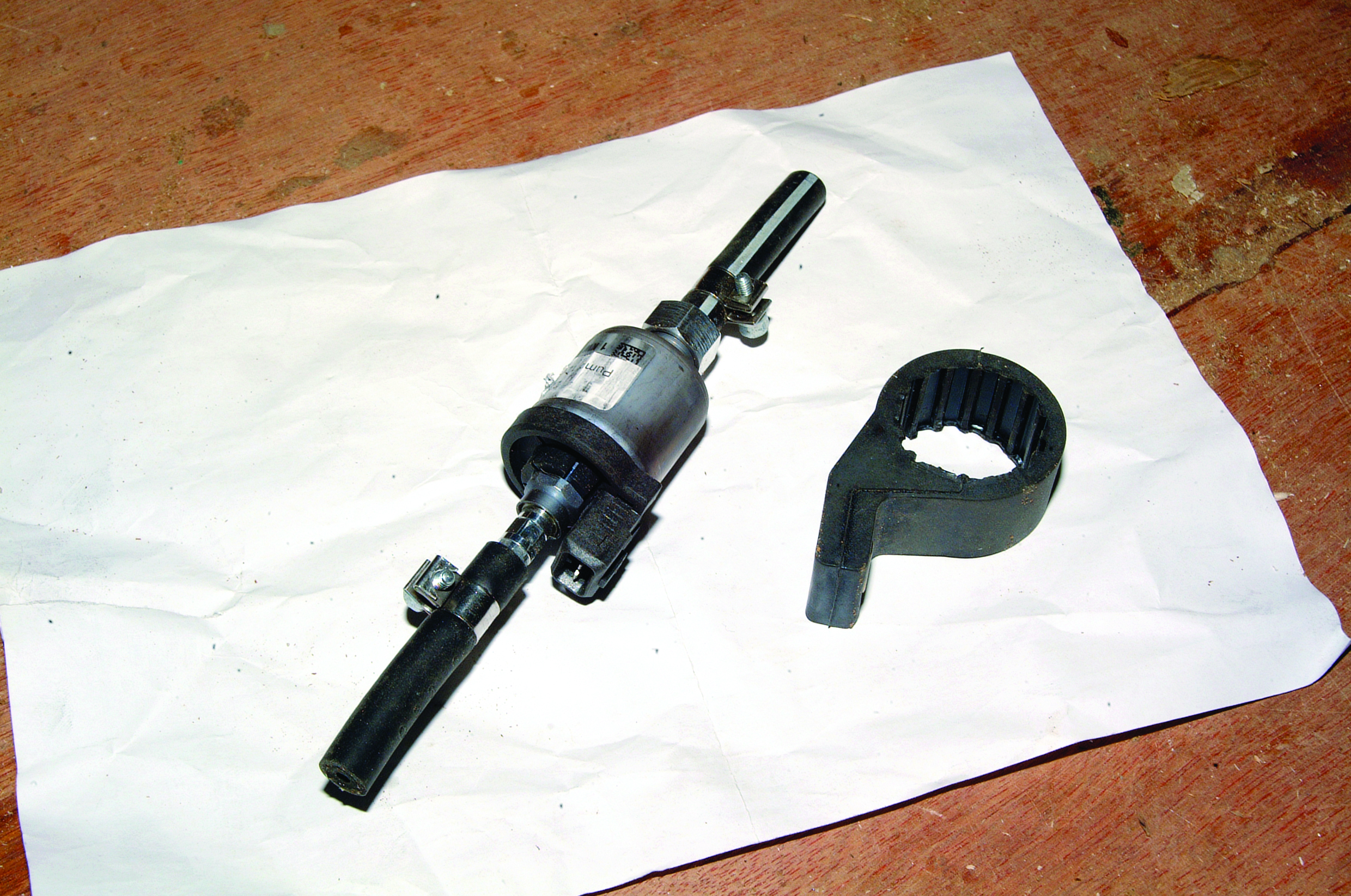
The fuel pump is supplied with a rubber mounting bracket that pushes over the pump body and holds the pump firmly while also cutting down on vibration. (Note the cable connector block on the pump. That is the outlet end, which is in the upper position when the pump is mounted).
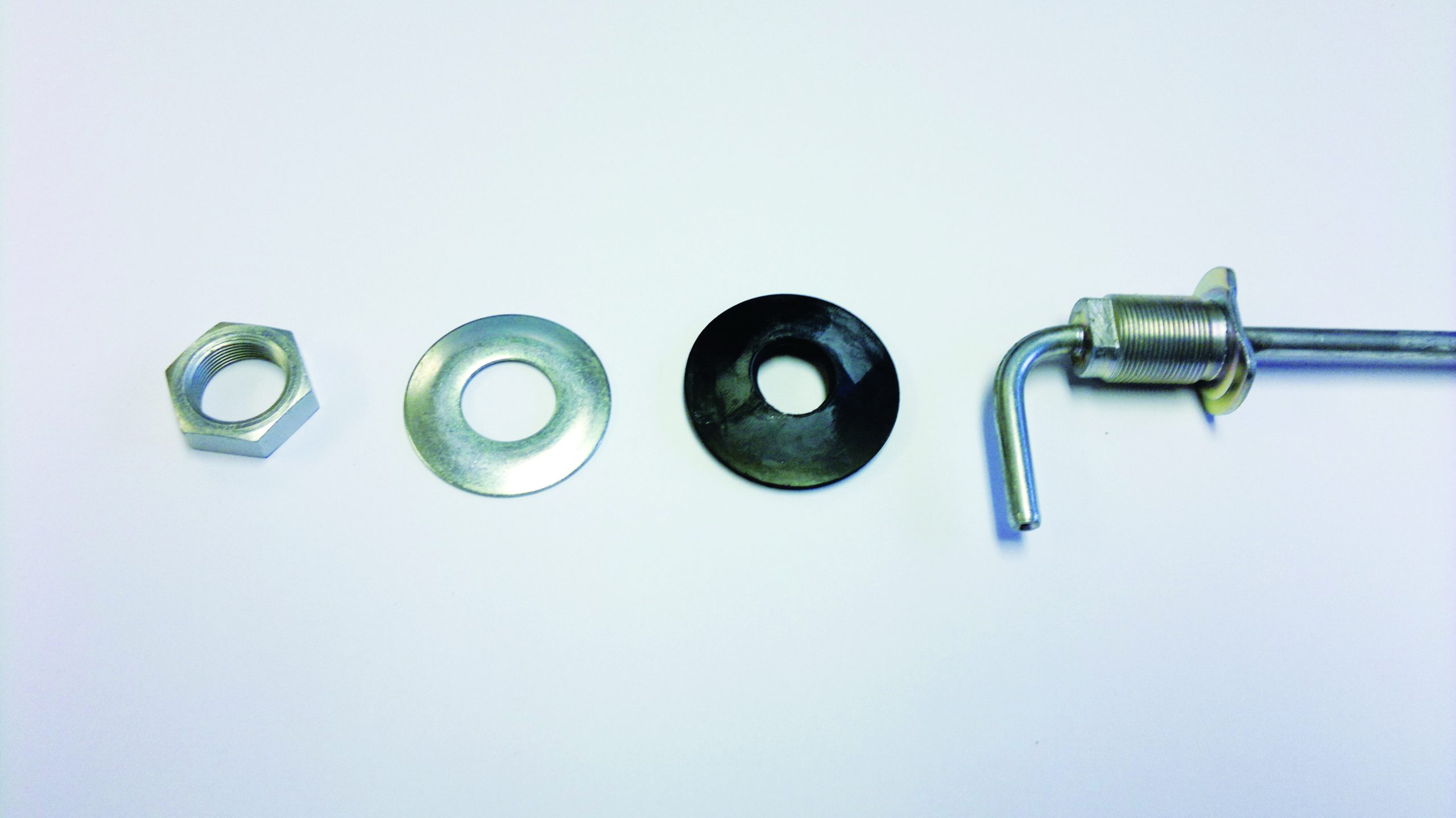
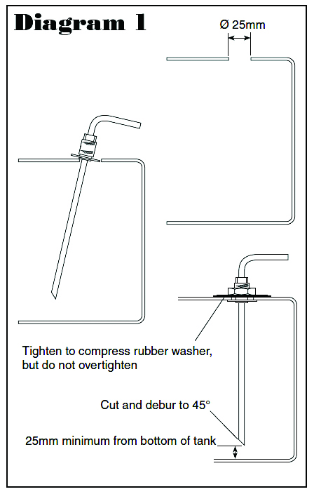
The fuel tank fitting supplied by Eberspacher is one of those clever items that can be fitted from outside the tank. The cutaway seen on the flange of the pickup pipe allows this to slip through the hole in the tank. In this case, as we fabricate our own tanks, there is always an inspection hatch included, and this means we were able to install it in a much smaller hole from the inside. (Keep the working area clean-oh dear! It was actually clean when the fitting was installed.)

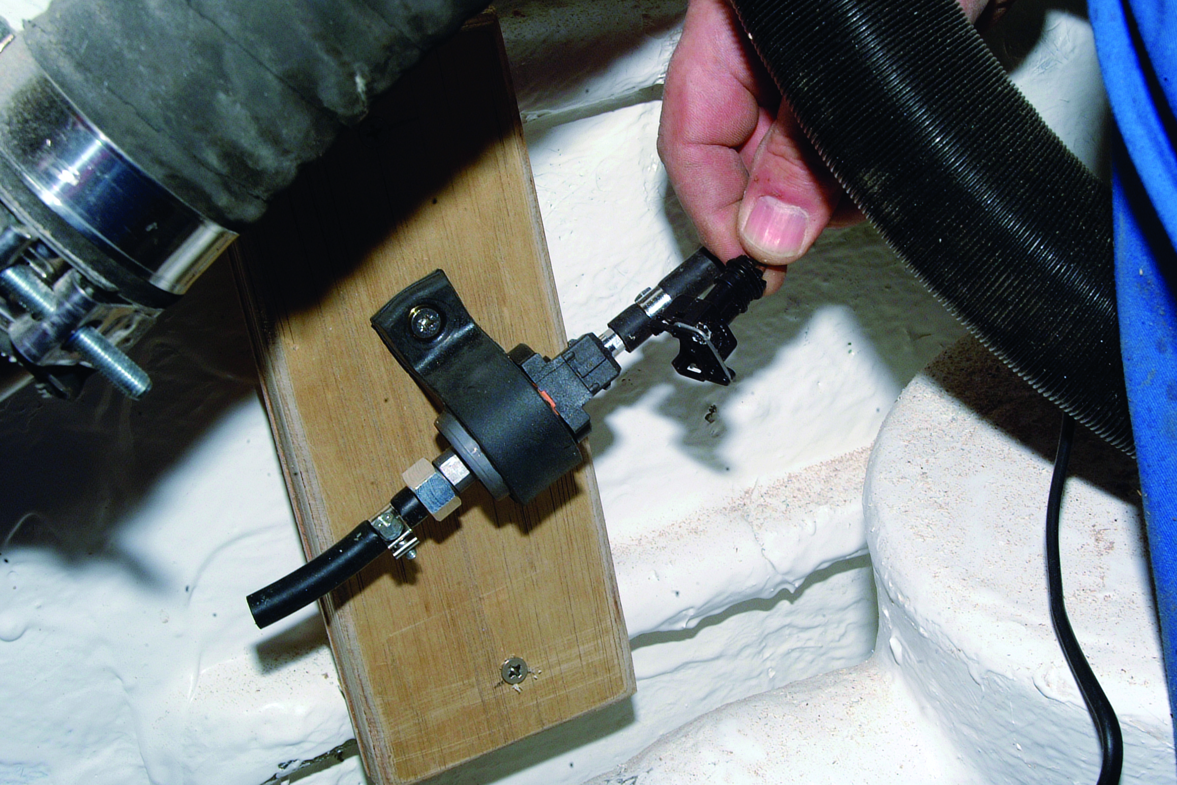
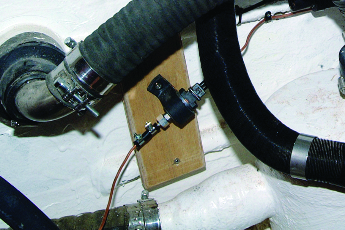
A simple bracket was screwed to two of the hull stringers as a base for mounting the pump. (This will be resin-coated later on, as it was fitted as an afterthought!) Once the pump is in position (with the cable connector on the upside of the pump), the plug on the loom can be connected.
NOTE: The pipework from the tank to the pump and on to the heater must run in an upwards direction to ensure that air bubbles cannot become trapped anywhere in the pipe run. This means that the position of the pump must be carefully chosen to ensure a smooth rise to the piping. (If the unit is to be used underway, you will need to allow for the boat/yacht heeling – Ed)
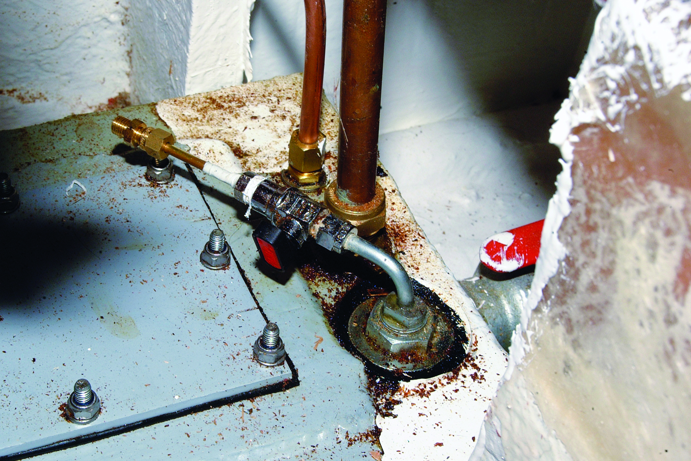
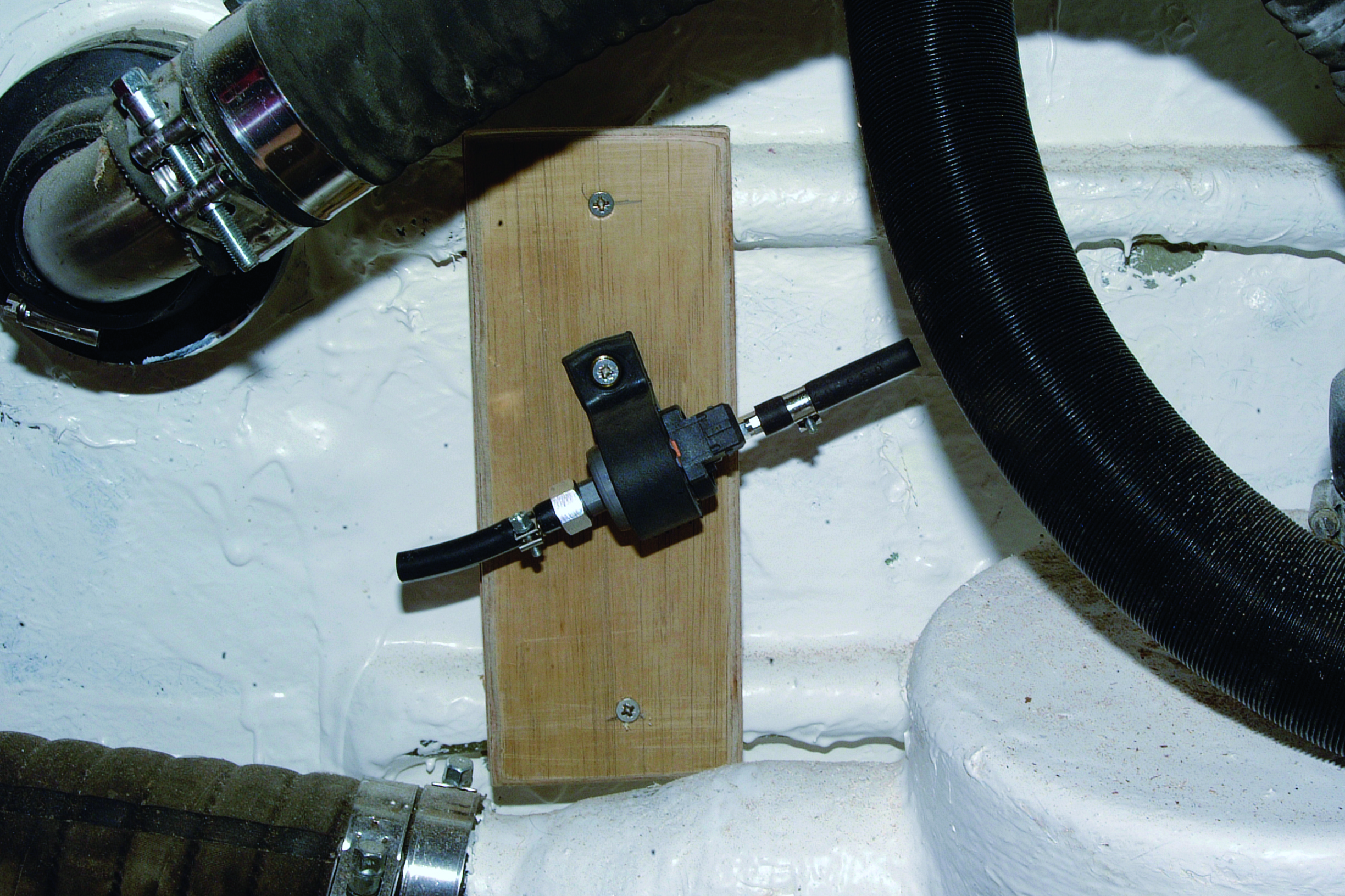
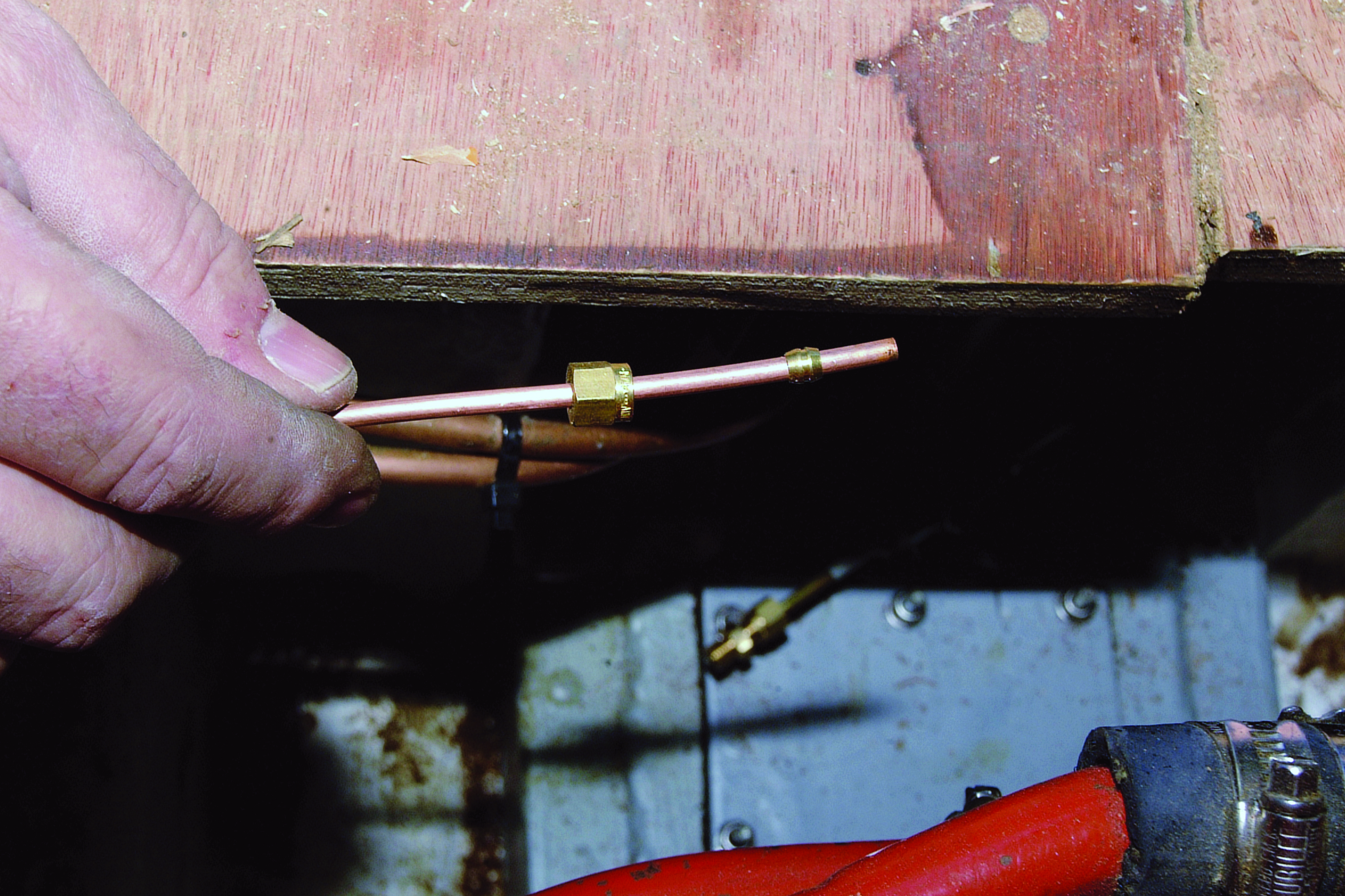
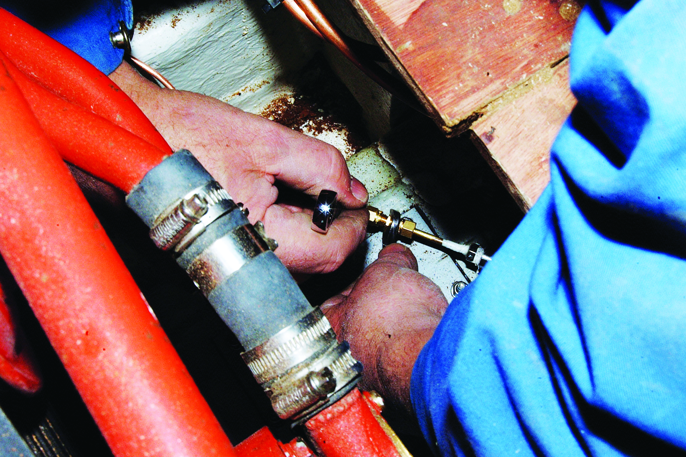
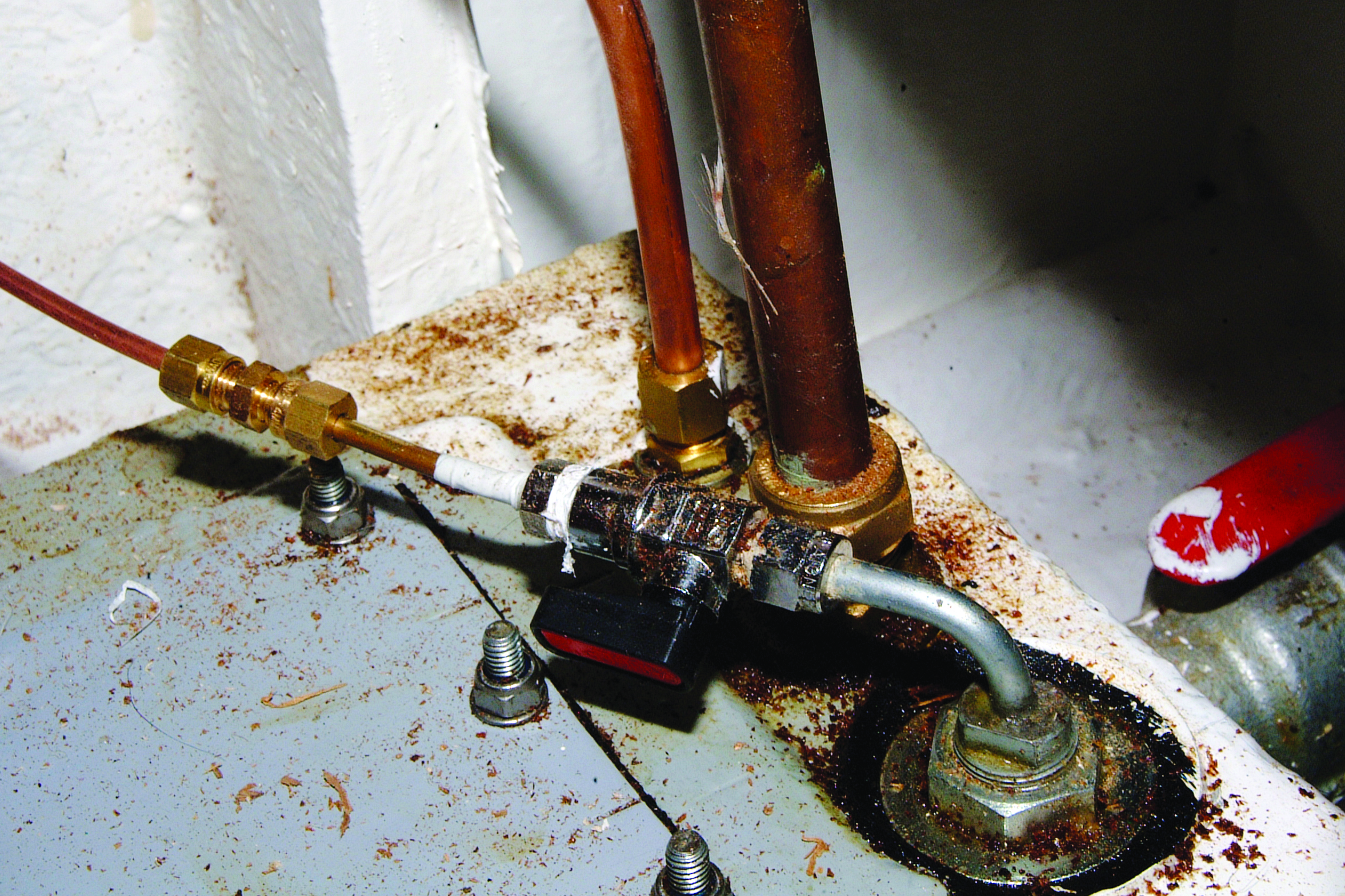
The piping can now be connected to the heater unit via one of the short lengths of hose and clips supplied. The piping can be similarly connected to the pump. At the tank end a compression fitting is normally used, although hose connectors are another option. The compression fitting is assembled in the normal way, taking care not to overtighten it and distort the olive. The finished connection with the shut-off valve fitted to the tank fitting in the open position, ready to go. The combustion air silencer was fitted to the heater inlet and clipped onto a stringer. (These do make a surprising difference in reducing exhaust noise). The pipework and cabling were also clipped down and generally tidied up.
Trunking insulation
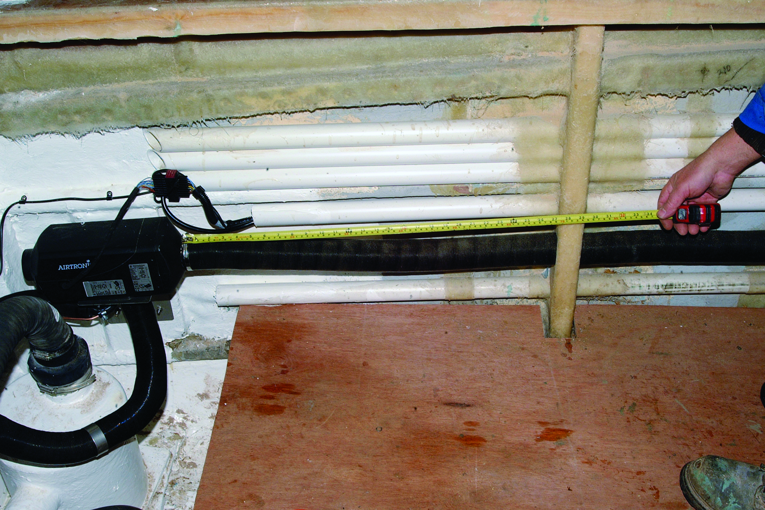
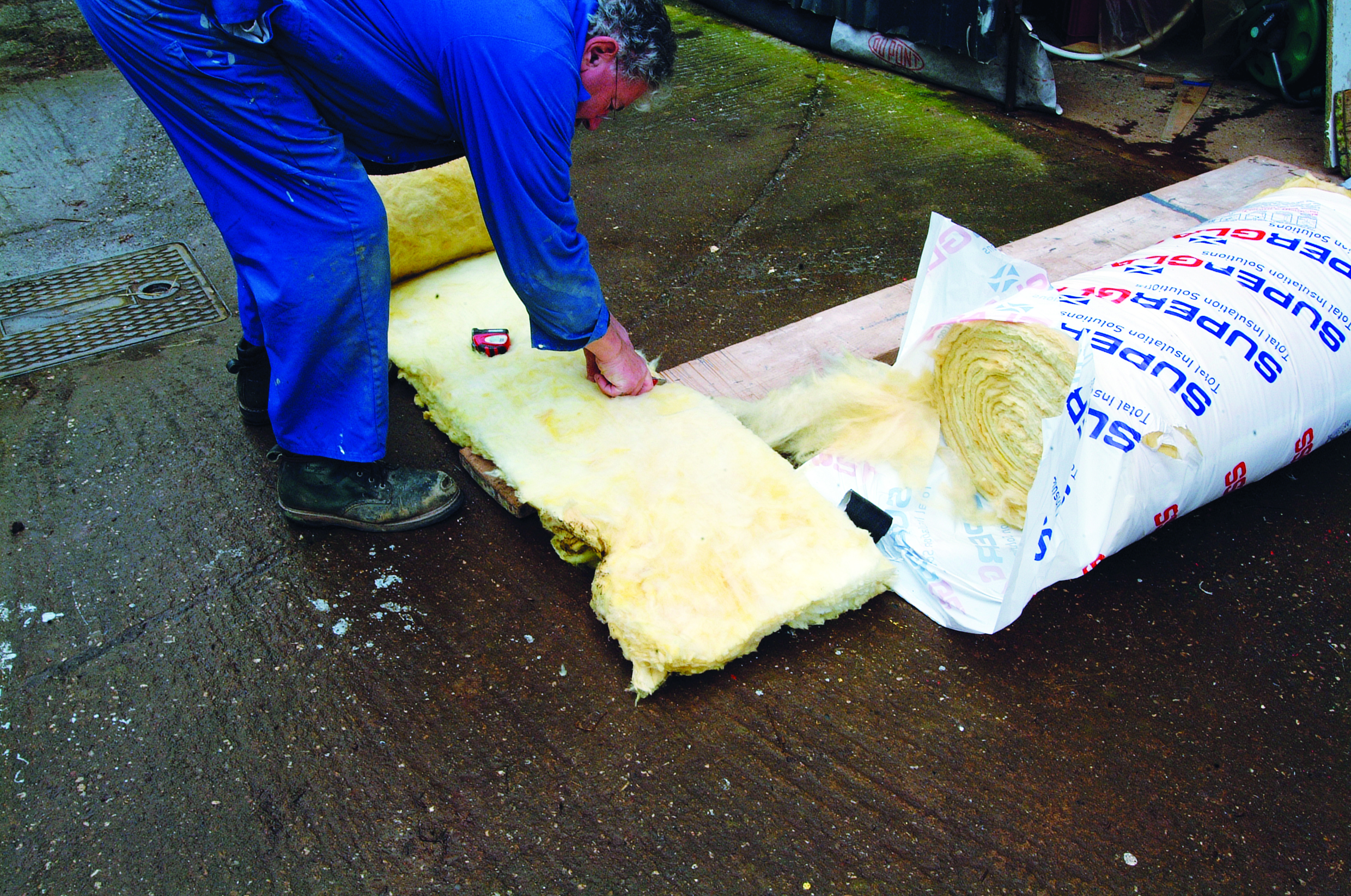
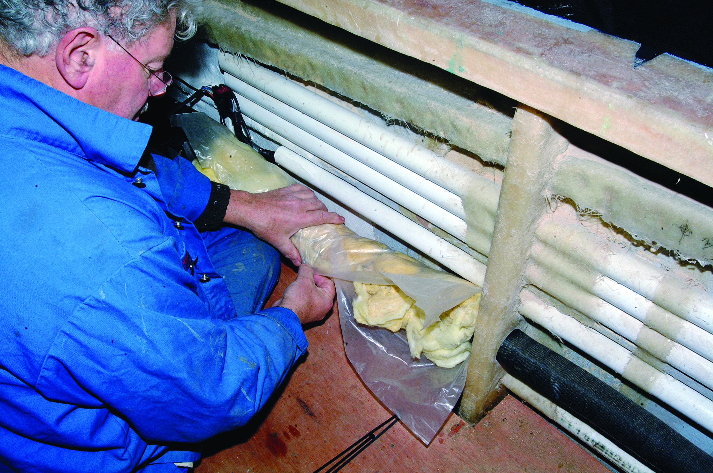
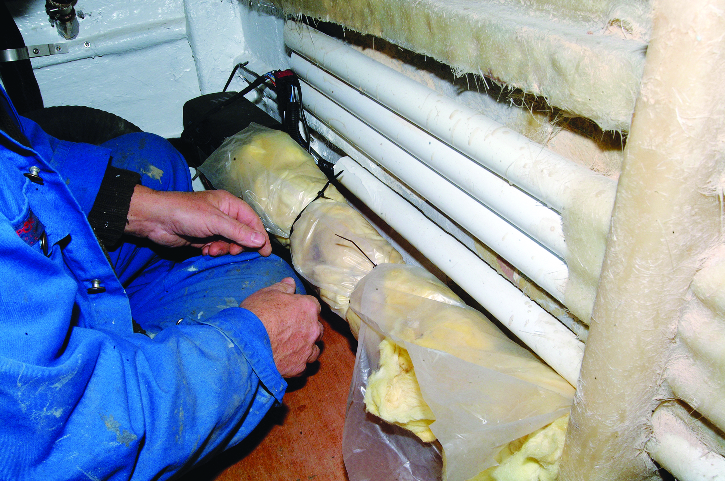
It is important to insulate the trunking to prevent all that lovely heat being dissipated through the walls of the trunking. The first step is to measure the length of insulation required. Various types of insulation can be used, but we find that the very cheap fibre-glass loft insulation works as well as anything. Begin by measuring and cutting the first section to length.
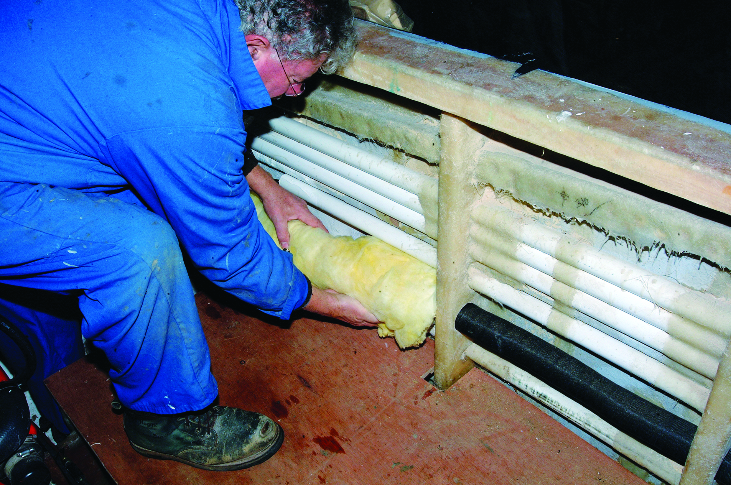
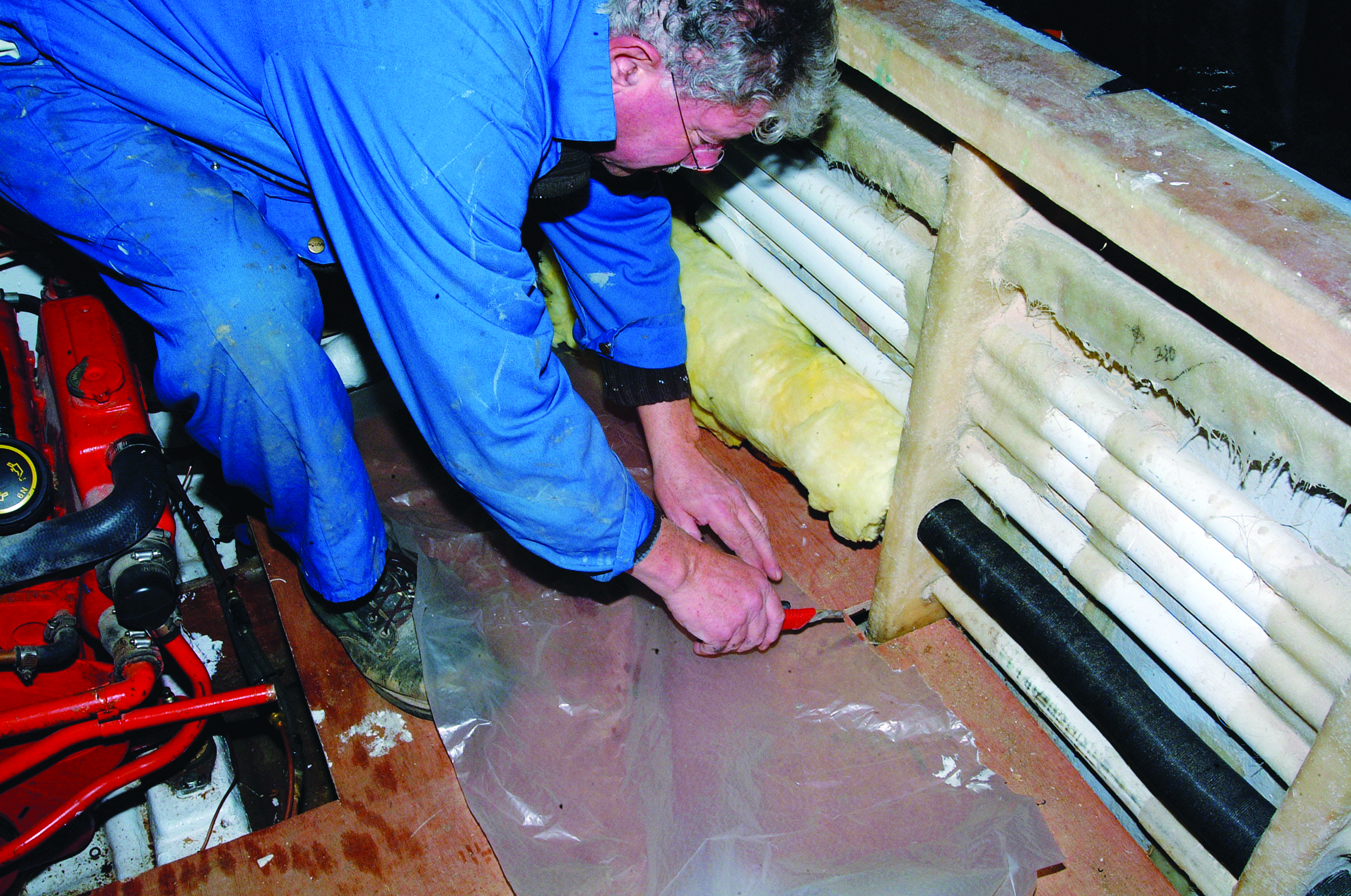
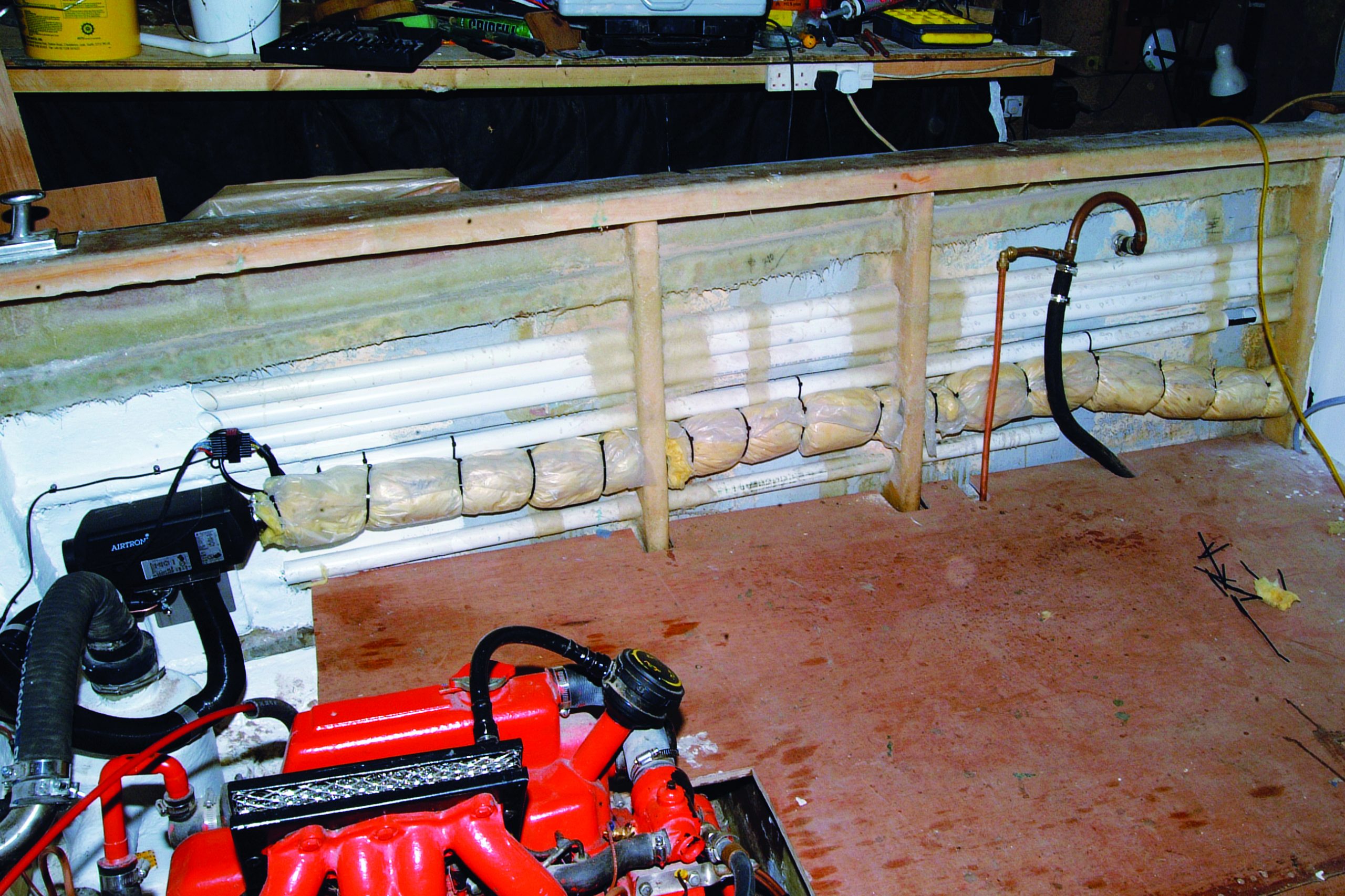
Wrap the insulation around the trunking so there are no gaps anywhere. (Gloves may be a good idea for those with sensitive skin and wear a mask.) Then cut a length of polythene to suit the section being insulated and wrap that around the insulation, making sure that it does not touch the trunking. We like to secure the polythene with cable ties, but duct tape is just as effective. Keep the joint at the bottom so that any moisture entering can drain out. Once the heating is on, any dampness will soon disperse. The completed external run of insulated trunking.
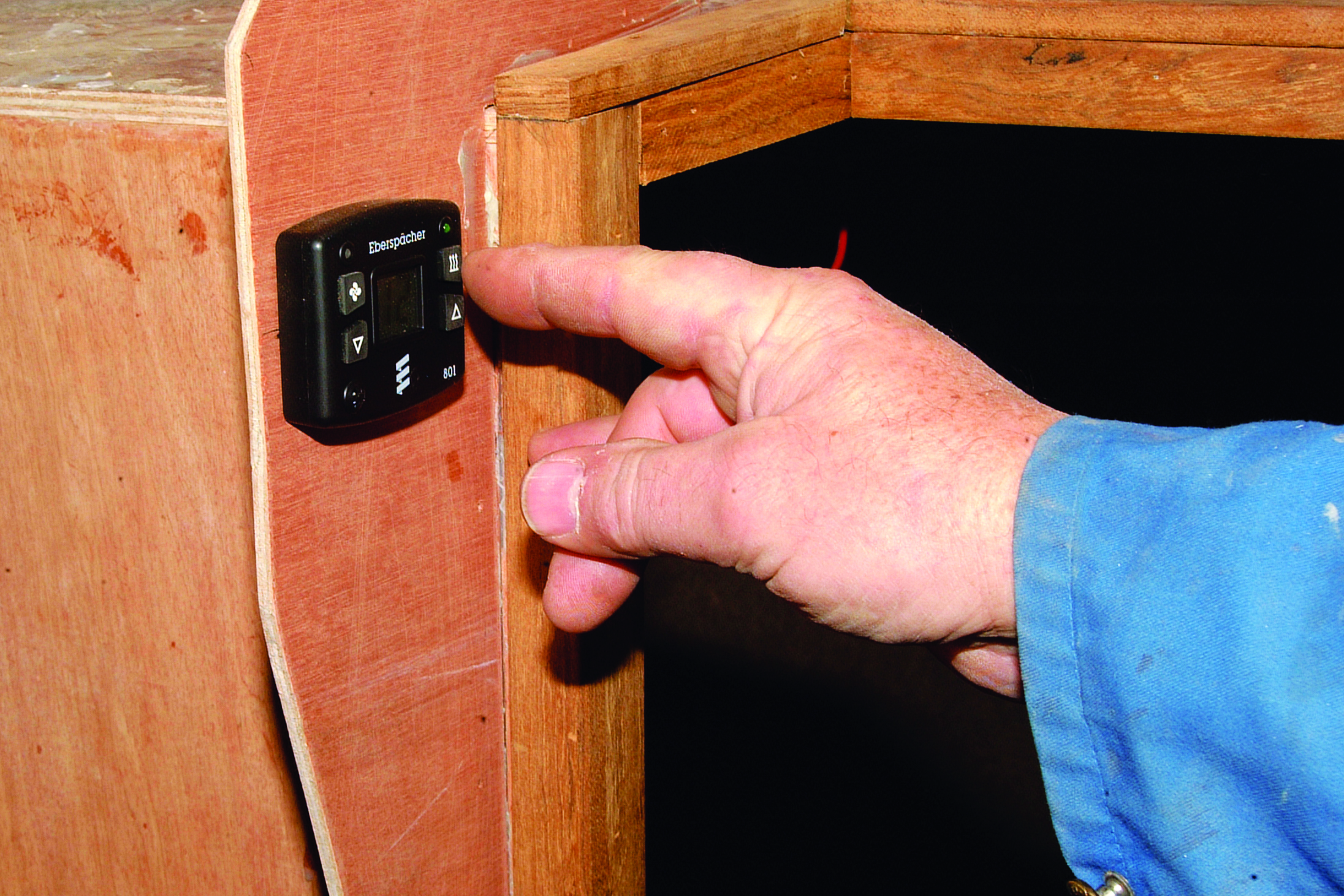
With the main battery power switched on it is time for the first firing. Starting is initiated by pressing the heat button, and the display will briefly show ‘ON’. NOTE: It usually takes a couple of start-up sequences to initially bring the fuel up from the tank to the heater, so don’t expect a first-time start. Also check the temperature setting by pressing either the up or down buttons.
And here is the proof of the pudding. I was expecting at least a small puff of smoke for the first start, but off it goes and nothing at all to show it is running – apart from the warmth!
Conclusion
A very straightforward and hassle-free installation.
Price
UK Cost: Airtronic D2 two outlet kit price: around £1,450.00 including VAT
Contact
Absolute Marine. Unit 1, 13 Highbrook Drive, East Tamaki, Auckland, New Zealand Tel: +64 (9) 273-9273 Email: sales@absolutemarine.co.nz