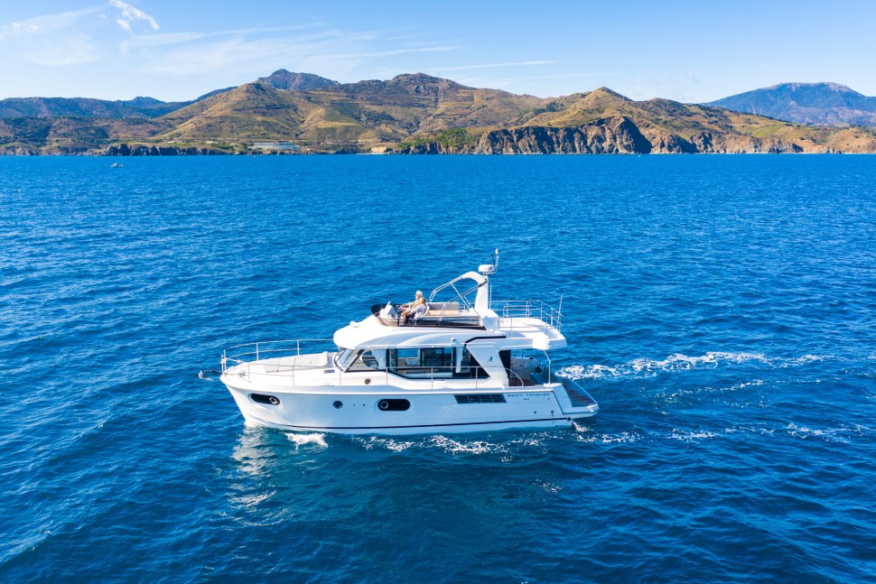
Now that we have fitted the two replacement outboards to Divecat, together with their Vibrastop anti-vibration system, the next item on the agenda is steering.
Because this is a twin-engine installation, there are several considerations. The size of the motors and the distance between the helm and the outboards means that a mechanical steering solution is not an option. This left us with three possibilities: hydraulic, hydraulic with power-assist, or electric.
It would have been fantastic to have installed the latest digital electric actuators, such as the Yamaha Helm Master EX system. These allow full digital control of the steering, and include the ability to implement joystick docking. However, the costs of this solution greatly exceeded my available budget and so I decided on a more conventional hydraulic system. The total cost was estimated to be about $2,500 for all the components, and this system allows a power-assist option to be added at a later date.
Next I needed to get the correctly-sized components. All outboard motors exhibit a twisting motion caused by the torque of the propeller, meaning the engine will require more force to turn in one direction than the other. When you have two identical motors this force is nearly doubled. Most twin installations therefore install a pair of counter-rotating motors, with the props spinning in opposite directions to one another. That way the twisting motion is cancelled out, and a properly set up twin configuration might require the same or even less steering force than a single outboard. The configuration is important to know when ordering the steering kit, to ensure it will be able to cope with the force required.

Depending on the positioning of the motors, a single actuator cylinder can be used, with a physical link between the motors. This was the original configuration on Divecat, with a single, grunty, hydraulic cylinder under the central walkway and a shaft connected to the motors on either end. The solution caused us some issues due to the shaft snagging when individually tilting the motors, but for smaller boats with clear space between the motors, it may be the simplest option.
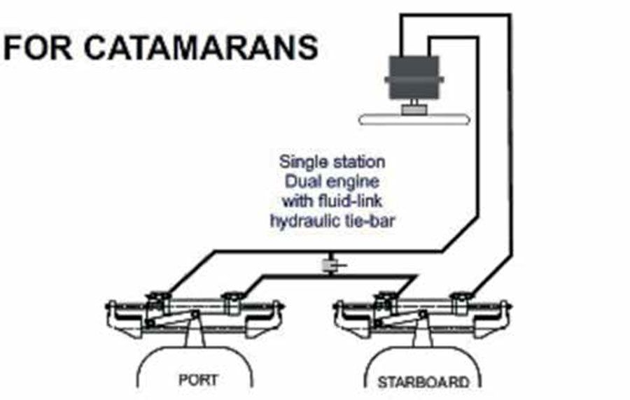
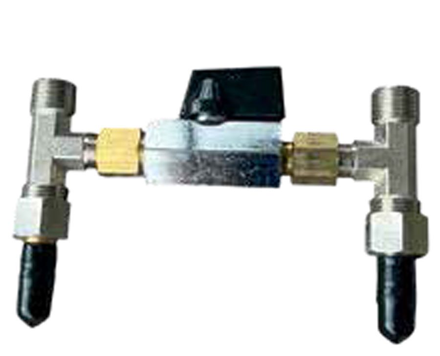
The alternative is individual smaller cylinders for each engine, and these may also be linked together with a rigid tie-bar. This presents the same problem where the tie-bar needs to move as the motors tilt or turn, so instead we are going with a fluid-link tie-bar configuration. This means we connect the cylinders in series, with the inner hydraulic connections of the cylinders simply joined together as per the diagram. The valve between them is used to align the motors, and this needs to be checked every couple of months in case it creeps out of alignment.
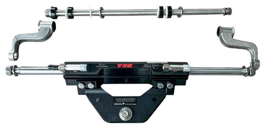
After researching available options, we purchased the twin-engine single-helm kit from BSA. This kit came with everything we needed and included nearly twice as much hose as we would require. Importantly, it also included a number of selffit hydraulic hose connectors, which means we can cut the supplied hoses exactly to the size we need rather than have to order custom-length hoses.
Since the kit came with extra hose and connectors, I shall be keeping these on board as part of the emergency spares kit. A split steering hose cannot be patched due to the hydraulic pressure, and failed steering means a tow home if not worse. By having extra hoses, connectors, and steering fluid available, I will be able to rectify any fault by simply replacing the faulty section of hose.
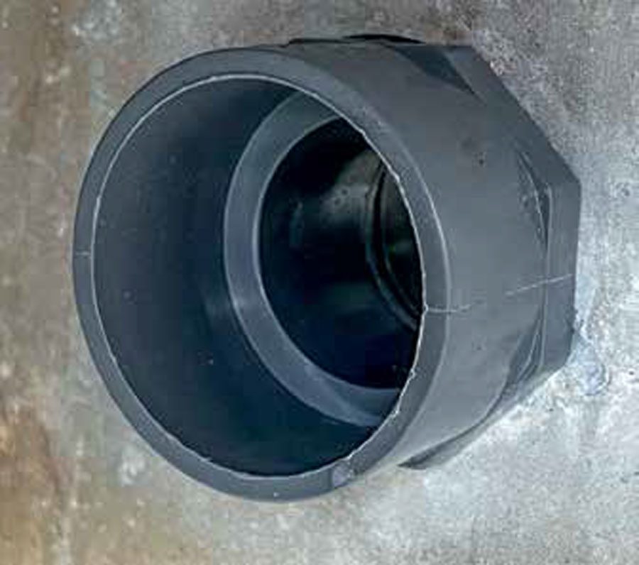
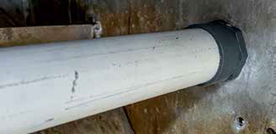
When working out the best way to route the hose I decided to add Ultraflex through-bulkhead hydraulic fittings to my installation. The hole where the hose passes through the transom is the most likely place for hose damage to occur, and these neat black plastic and stainless-steel fittings provide a secure and robust connection that is also watertight. The only other items needed but not in the kit were a suitable steering wheel, and the correct amount of hydraulic fluid.

Installing brand new equipment is always a pleasure compared to servicing existing stuff, since you don’t need to deal with seized threads or dirty and damaged parts. The only question was where to locate the bulkhead fittings in the transom, since they need to allow the free movement of the hoses through the full range of motor movement without kinking. After some consideration, I located them in the inner side of the outboard well, a generous height above the waterline and clear of any engine movement. The supplied template and a 40mm hole-saw were used to cut out the right shape, and each fitting was easy to install.
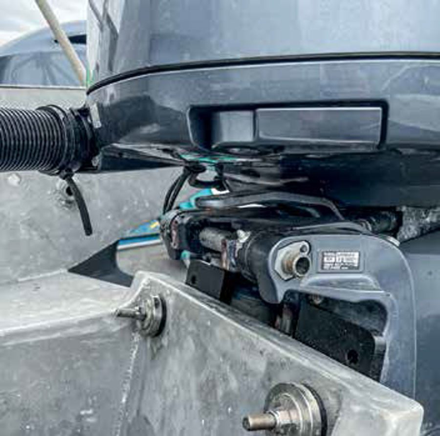
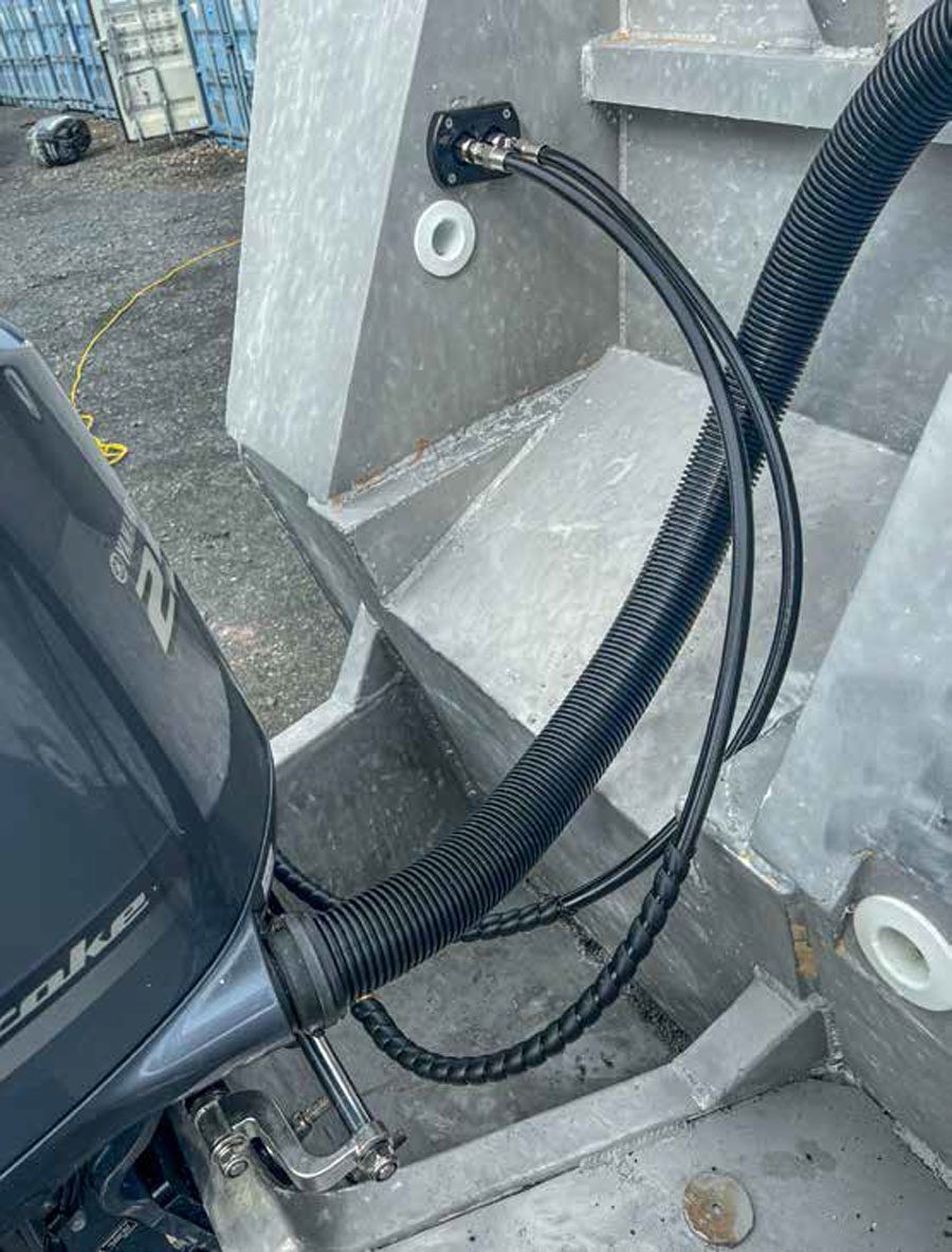
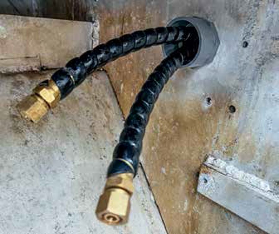
I then cut the short hoses that run from the engine to the fitting, allowing enough length to accommodate engine turn and tilt. Following the instructions, I first installed one of the new connectors to the cut end before fitting the swaged end of the hose to the steering cylinder on the motor. After repeating this for the second hose, it all looked neat and tidy.
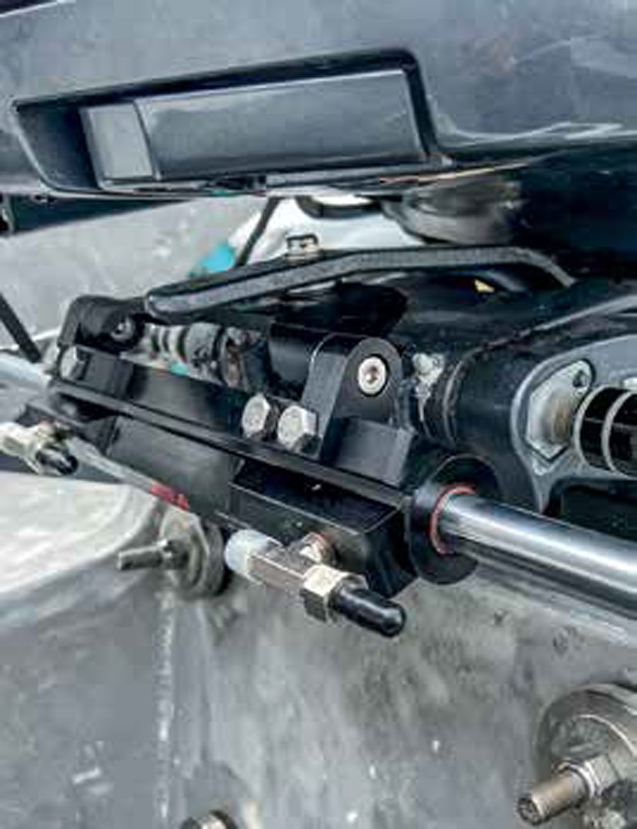
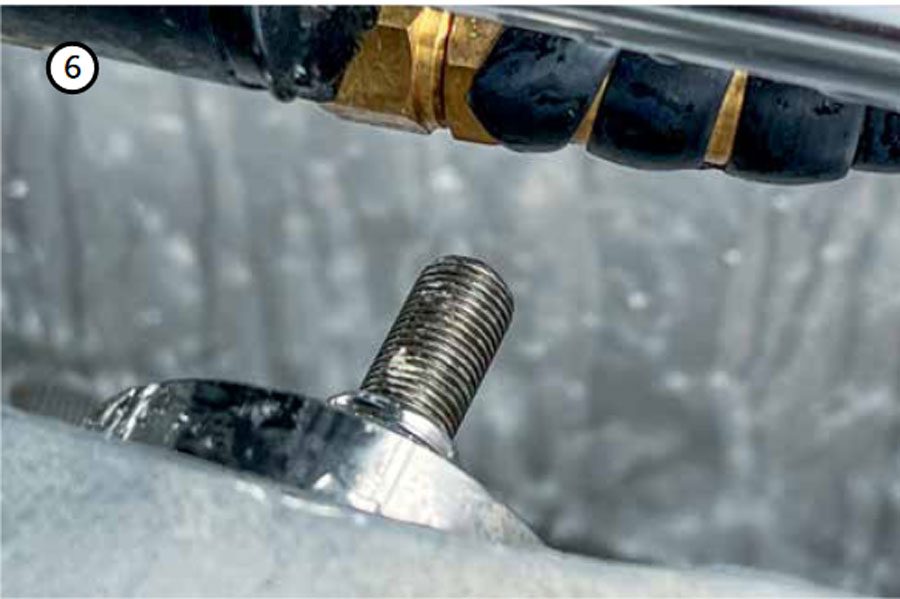
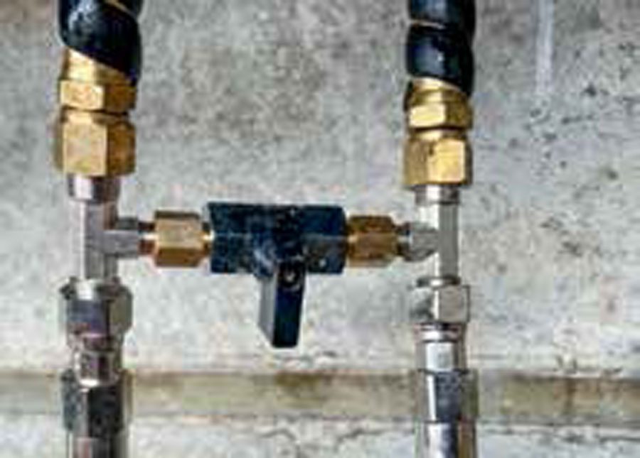
It was only when I tried tilting the motor that a snag arose. The topmost engine mounting bolt through the transom protruded enough to just catch the outward-facing connector of the steering cylinder. This would not do – a few dozen cycles and the hose would be damaged enough to start leaking. I was reluctant to cut the mounting bolt shorter. So instead I swapped the bleed valve and inlet to different sides of the T-connector, as per the photo.
The meant that the incoming hydraulic hoses were now both coming from the inside of the cylinder, which would make a slightly less tidy installation with hoses crossing over each other. However it did mean that the connectors would not snag, no matter what position the outboard was in when it was tilted up. Function over form seemed a good compromise under the circumstances.
Inside the hull I now had to implement the fluid link between the motors, and run hoses up to the helm. Again this was simple enough, cutting hose to the required length and installing the hydraulic connectors. The alignment valve is installed between the fluid link hose and one of the feeder hoses from the helm, so it effectively enables the hydraulic fluid to completely bypass one of the engines. Since this needs to be checked from time to time, I made sure the valve was easily accessible through one of the deck hatches.
To simplify the hose runs and also install the valve for the fluid link I brought both the starboard hoses through the bulkhead between the port and starboard hulls. I wanted to maintain the watertightness between the hulls and hence needed more bulkhead fittings to safely pass those hoses through. Since this is a permanent connection that will have no movement I purchased two plastic through-bulkhead strain relief fittings from Absolute Marine. These fitted tightly to the hose and did not require additional joiners.
Running the hoses forward to the helm was simple enough, although I elected to run these the whole way through a long length of plastic conduit from the stern to just under the helm. This meant there were absolutely no bulkhead or other pressure points where the hose could wear through, while it also maintained the watertightness between the compartments. At the helm, the hoses come up through an existing opening in the floor.
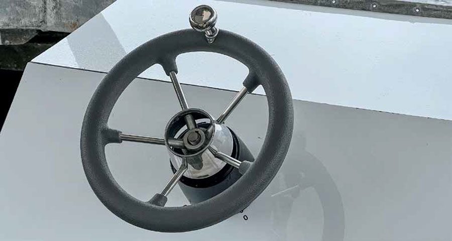
In the meantime, I had started rebuilding the helm station, covering the exterior with a plywood and fibreglass laminate. This allowed me to fit the helm pump and run the hydraulic tubes up the inside the helm pedestal. To keep things neat, I used P-clips to hold the hoses to the side on the helm pedestal and feed into the pump from the side rather than from below.
And that was everything installed. The last remaining step was to fill the system with hydraulic fluid, bleed the air out and then align the motors precisely. The kit came with instructions for filling and bleeding the system, and these were easy to follow. A dual-engine system is slightly more complex to bleed than a single one. Basically, you fill the helm pump with fluid, and use the bleed valves on the outside of each cylinder to individually fill the helm-to-stern long hoses with fluid. Then you close those bleed valves and use the bleed valves on the inner side of the cylinders to fill each of them with fluid. Lastly the fluid link hose and valve is filled, using the bleed valves on the link to purge all the air out of that section. When done correctly there is no air trapped anywhere.
The manual was not very clear about the process for aligning the motors up, but a quick Google search came up with some suggestions. The simplest seemed to be to turn the steering hard to one side until the first motor reaches full lock. Then you open the alignment valve and continue to turn the helm until both motors are at full lock. The valve is then closed and the motors should now be properly aligned. This process worked perfectly for me, and they should stay in alignment unless one of the cylinders develops a leak.
The total costs for my twin-outboard, single-helm system, including initial kit, steering wheel, bulkhead fittings and hydraulic fluid was $3,099. BNZ