There are several types of propeller shaft seal, from the traditional stuffing box to modern derivatives such as the PSS shaft seal used here.
Until recently, my 12m cruiser has had a stuffing box, Deep Sea Seal and Halyard Shaft Seal. I was very happy with the Halyard seal even though it had exceeded it’s design life by several years, but unfortunately Halyard no longer make them, so I had to find an alternative. The Deep Sea Seal was OK, and apart from a couple of sudden inrushes of water caused by sediment on the faces, performed well. The Deep Sea Seal on the wing engine shaft, which only does a few hours running per year, was still in more or less new condition but, at some 15 years old, I decided it should be changed along with the main shaft seal.
The PSS seal has been around for some years and is very popular in the UK and Europe, so I decided to try these. They are well-engineered and relatively easy to install. However, fitting any shaft seal requires disconnection of the propeller shaft from the gearbox to allow the shaft to move back sufficiently for removal of the old seal and fitting of the new. Obviously, the boat should be on hardstand first – you can’t do it afloat.
The type of coupling decides the method of disconnection. Sliding the shaft back often means removing the propeller so, although the job is basically easy, there is quite a lot of subsidiary work involved. This provides a good opportunity to tackle other stern-gear related items such as a propeller overhaul, shaft bearing renewal, and rope-cutter servicing.
- Advertisement, article continues below -
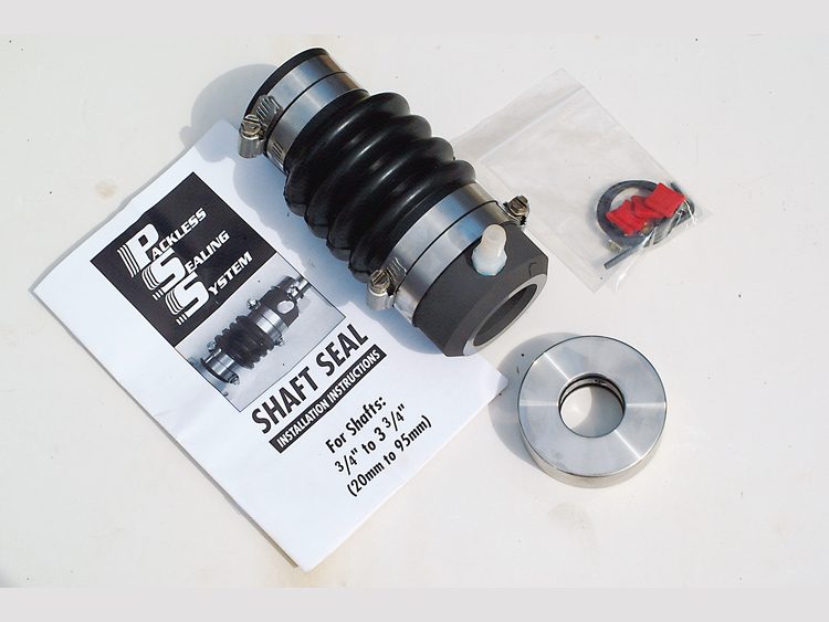
1. The PSS seal comprises the main assembly with the bellows and carbon faceplate, secured together with hose clips and the stainless-steel rotor containing the two ‘O’ ring seals that prevent water ingress past the rotor. An Allen key, spare ‘O’ rings and grub screws are also included.
The PSS seal comprises the main assembly with the bellows and carbon faceplate, secured together with hose clips and the stainless-steel rotor containing the two ‘O’ ring seals that prevent water ingress past the rotor. An Allen key, spare ‘O’ rings and grub screws are also included.
External preparation
2. With the rudder directly aft of the propeller, one or other had to be removed to allow the shaft to slide back. As the prop’ was due for repair this was the obvious choice.
With the rudder directly aft of the propeller, one or other had to be removed to allow the shaft to slide back. As the prop’ was due for repair this was the obvious choice. 3. The ‘Proprotector’ rope cutter was removed first and although covered in crud was still dangerously sharp!
- Advertisement, article continues below -
The ‘Proprotector’ rope cutter was removed first and although covered in crud was still dangerously sharp!
4. The 10 year old ‘Propro’ was cleaned by scraping with a wood chisel and found to be in perfect condition.
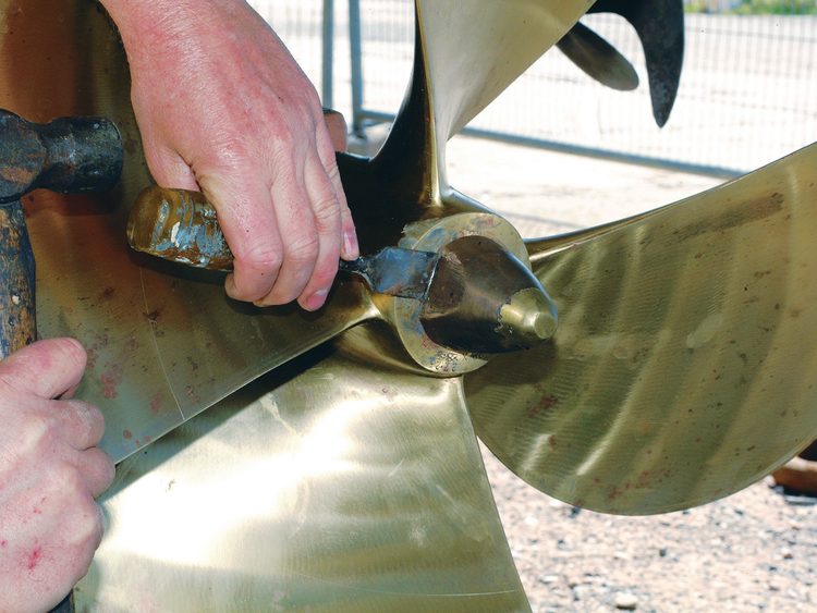
The 10 year old ‘Propro’ was cleaned by scraping with a wood chisel and found to be in perfect condition. 5. The first step in propeller removal is to knock back the tab washer (or remove the split spin as appropriate).
The first step in propeller removal is to knock back the tab washer (or remove the split spin as appropriate).
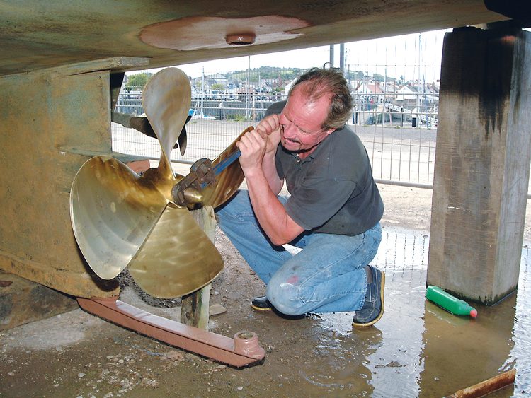
6. Place a block of wood under one blade and using a large spanner or pipe wrench, undo the propeller nut.
Place a block of wood under one blade and using a large spanner or pipe wrench, undo the propeller nut.
7. Don’t hammer the prop’ off – at thousands of dollars apiece, you don’t want to damage it! Use a puller (this one was £14 [$30] on Ebay). A puller will generally do the job by itself, but if not, you can try gently heating the prop’ boss with a blow lamp. (Note: heating one of the new geared props is not recommended as it may damage the grease and seals inside.) However, if it still refuses to budge, seek local professional assistance from someone like Henleys Propellers.
Don’t hammer the prop’ off – at thousands of dollars apiece, you don’t want to damage it! Use a puller (this one was £14 [$30] on Ebay). A puller will generally do the job by itself, but if not, you can try gently heating the prop’ boss with a blow lamp. (Note: heating one of the new geared props is not recommended as it may damage the grease and seals inside.) However, if it still refuses to budge, seek local professional assistance from someone like Henleys Propellers.
8. Leave the prop nut on a few threads to prevent the propeller dropping off the shaft, tap the end of the puller, and tighten until the prop comes free of the taper.
- Advertisement, article continues below -
Leave the prop nut on a few threads to prevent the propeller dropping off the shaft, tap the end of the puller, and tighten until the prop comes free of the taper.
9. Lift the prop away ready to go off for repair. If you have heated it, take care as it may still be hot.
Lift the prop away ready to go off for repair. If you have heated it, take care as it may still be hot.
Internal preparation
16. This is a good opportunity to replace worn shaft bearings by first completely removing the prop shaft. (I also removed the rudder to attend to some damaged epoxy around the rudder tube).
This is a good opportunity to replace worn shaft bearings by first completely removing the prop shaft. (I also removed the rudder to attend to some damaged epoxy around the rudder tube).
17. Remove the bearing grub screws. With phenolic-bodied bearings, simply break them up using a sharp wood chisel. For bronze-bodied bearings use an internal puller. If you have a GRP stern tube, use a puller made up from a threaded rod(s) and coupling nuts instead, or several nuts and a lathe-cut disk.
Remove the bearing grub screws. With phenolic-bodied bearings, simply break them up using a sharp wood chisel. For bronze-bodied bearings use an internal puller. If you have a GRP stern tube, use a puller made up from a threaded rod(s) and coupling nuts instead, or several nuts and a lathe-cut disk. 18. Once split open, Phenolic-bodied bearings will easily pull out of the tube. (Thorden-type plastic shaft bearings are first frozen-cooled in ice or liquid nitrogen and then simply slid into place – Ed) Fit the new bearing, refit the grub screws and reinstall the prop shaft.
Once split open, Phenolic-bodied bearings will easily pull out of the tube. (Thorden-type plastic shaft bearings are first frozen-cooled in ice or liquid nitrogen and then simply slid into place – Ed) Fit the new bearing, refit the grub screws and reinstall the prop shaft. Installing the PSS shaft seal
19. Use fine wet and dry sandpaper to remove any burrs from the shaft, eg 400, 800 or 3000 grit.
Use fine wet and dry sandpaper to remove any burrs from the shaft, eg 400, 800 or 3000 grit. 20. Clean and degrease the shaft and shaft tube.
Clean and degrease the shaft and shaft tube.
21. Slacken the securing hose clips on the open end of the bellows and slip the assembly over the shaft and onto the shaft tube.
Slacken the securing hose clips on the open end of the bellows and slip the assembly over the shaft and onto the shaft tube.
22. Screw the grub screws into the rotor so that they protrude inside. This ensures any swarf in the threads is removed. Then wind them back so they don’t score the shaft during fitting.
Screw the grub screws into the rotor so that they protrude inside. This ensures any swarf in the threads is removed. Then wind them back so they don’t score the shaft during fitting. 23. Apply copious amounts of soapy water to the rotor and the shaft to allow the internal ‘O’ rings to slide easily along the shaft.
Apply copious amounts of soapy water to the rotor and the shaft to allow the internal ‘O’ rings to slide easily along the shaft.
24. Slide the rotor onto the shaft until it is just touching the carbon face of the bellows assembly.
Slide the rotor onto the shaft until it is just touching the carbon face of the bellows assembly. 25. Ensure the bellows assembly is in line with the shaft and then tighten the securing hose clips.
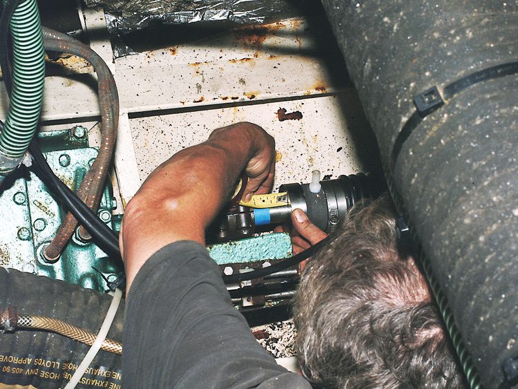
Ensure the bellows assembly is in line with the shaft and then tighten the securing hose clips. 26. With the rotor just touching the uncompressed bellows assembly, fix a piece of tape to the shaft to mark the position of the rotor and then slide the rotor down the shaft, compressing the bellows.
With the rotor just touching the uncompressed bellows assembly, fix a piece of tape to the shaft to mark the position of the rotor and then slide the rotor down the shaft, compressing the bellows.
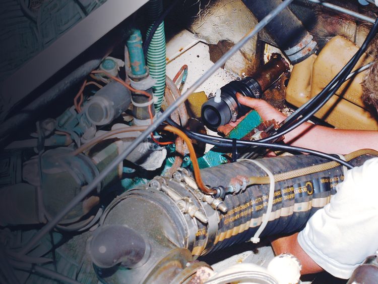
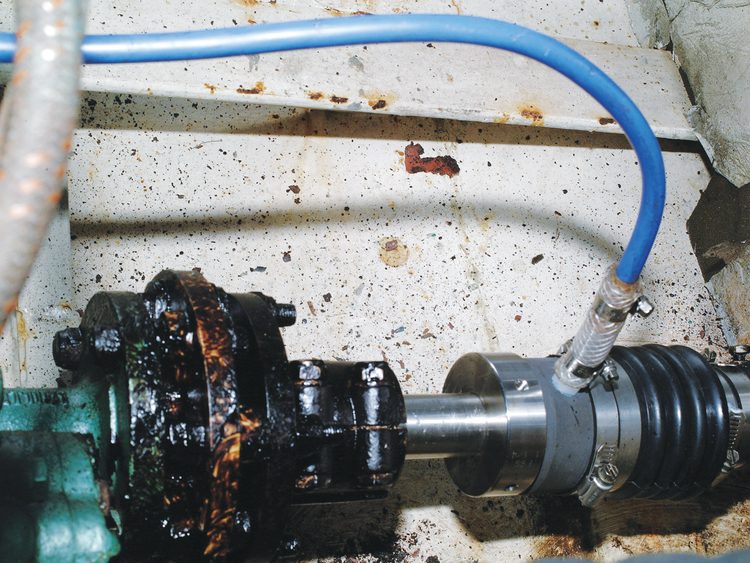
27. The stern tube water feed can now be connected to the spigot on the PSS seal. Always use flexible hose for the final connection to ensure there is no pressure applied to the seal by the hose. Finally, reconnect the shaft to the gearbox.
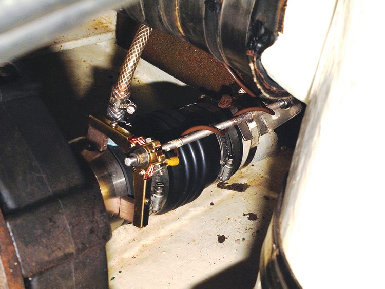
The stern tube water feed can now be connected to the spigot on the PSS seal. Always use flexible hose for the final connection to ensure there is no pressure applied to the seal by the hose. Finally, reconnect the shaft to the gearbox. 28. Refit the ‘Electro Eliminator’. In this case the original No. 1 Eliminator would not fit over the PSS seal, so I replaced it with the larger No. 2 and arranged for it to run on the rotor itself.
Refit the ‘Electro Eliminator’. In this case the original No. 1 Eliminator would not fit over the PSS seal, so I replaced it with the larger No. 2 and arranged for it to run on the rotor itself.
Note: You may have to gently tighten the grub screws to prevent the bellows pushing the rotor back under compression. Referring to the compression table in the instructions (in this case one inch – the good old Yanks still use real measurements!), move the rotor against bellows compression until the measurement between tape and rotor face is achieved. Now tighten the grub screws as tight as possible using the supplied Allen key. A second set of grub screws is provided to use as locking screws and these are screwed in on top of the first set and tightened.
External completion
29. Grease the prop shaft taper and refit the Woodruff key into the slot. Refit the prop taking care to keep your knees together when lifting it!
Grease the prop shaft taper and refit the Woodruff key into the slot. Refit the prop taking care to keep your knees together when lifting it!
30. If using a tab washer, bend out the tab so that it locates into the slot in the propeller. Fit the tab washer and screw on the prop nut.
If using a tab washer, bend out the tab so that it locates into the slot in the propeller. Fit the tab washer and screw on the prop nut.
31. Tighten the nut securely.
Tighten the nut securely.
32. Finally knock over the tabs on both sides of the tab washer to lock the nut securely.
Finally knock over the tabs on both sides of the tab washer to lock the nut securely. Note: When the boat is returned to the water ease back the PSS bellows to allow air trapped in the shaft tube to escape before running the engine in gear. The water flow into the seal with the engine running must be checked before any serious motoring is done. This must be measured, and if necessary, adjusted so that the seal gets the right amount at cruising speeds. Propeller specialists, like Henleys for example, have a specific number of litres per minute for their shaft seals. Too little and the seal bearings overheat, too much and the seals get damaged.
Expect a fine mist from the shaft seal for the first hour of running until it is bedded in.
If it continues to leak after running-in, increase the bellows pressure slightly until it stops.
Contact and further information
PSS shaft seals
Contact your local marine supplier.
MG Duff Electro-Eliminator
sales@mgduff.co.uk
Note
This article pertains specifically to PSS seals. Many New Zealand boaties use the Henleys’ Kiwi Seal or Chatfield seals, which use a completely different method of sealing the shaft.
With the rotor just touching the uncompressed bellows assembly, fix a piece of tape to the shaft to mark the position of the rotor and then slide the rotor down the shaft, compressing the bellows.
27. The stern tube water feed can now be connected to the spigot on the PSS seal. Always use flexible hose for the final connection to ensure there is no pressure applied to the seal by the hose. Finally, reconnect the shaft to the gearbox.
The stern tube water feed can now be connected to the spigot on the PSS seal. Always use flexible hose for the final connection to ensure there is no pressure applied to the seal by the hose. Finally, reconnect the shaft to the gearbox. 28. Refit the ‘Electro Eliminator’. In this case the original No. 1 Eliminator would not fit over the PSS seal, so I replaced it with the larger No. 2 and arranged for it to run on the rotor itself.
Refit the ‘Electro Eliminator’. In this case the original No. 1 Eliminator would not fit over the PSS seal, so I replaced it with the larger No. 2 and arranged for it to run on the rotor itself.
Note: You may have to gently tighten the grub screws to prevent the bellows pushing the rotor back under compression. Referring to the compression table in the instructions (in this case one inch – the good old Yanks still use real measurements!), move the rotor against bellows compression until the measurement between tape and rotor face is achieved. Now tighten the grub screws as tight as possible using the supplied Allen key. A second set of grub screws is provided to use as locking screws and these are screwed in on top of the first set and tightened.
External completion
29. Grease the prop shaft taper and refit the Woodruff key into the slot. Refit the prop taking care to keep your knees together when lifting it!
Grease the prop shaft taper and refit the Woodruff key into the slot. Refit the prop taking care to keep your knees together when lifting it!
30. If using a tab washer, bend out the tab so that it locates into the slot in the propeller. Fit the tab washer and screw on the prop nut.
If using a tab washer, bend out the tab so that it locates into the slot in the propeller. Fit the tab washer and screw on the prop nut.
31. Tighten the nut securely.
Tighten the nut securely.
32. Finally knock over the tabs on both sides of the tab washer to lock the nut securely.
Finally knock over the tabs on both sides of the tab washer to lock the nut securely. Note: When the boat is returned to the water ease back the PSS bellows to allow air trapped in the shaft tube to escape before running the engine in gear. The water flow into the seal with the engine running must be checked before any serious motoring is done. This must be measured, and if necessary, adjusted so that the seal gets the right amount at cruising speeds. Propeller specialists, like Henleys for example, have a specific number of litres per minute for their shaft seals. Too little and the seal bearings overheat, too much and the seals get damaged.
Expect a fine mist from the shaft seal for the first hour of running until it is bedded in.
If it continues to leak after running-in, increase the bellows pressure slightly until it stops.
Contact and further information
PSS shaft seals
Contact your local marine supplier.
MG Duff Electro-Eliminator
sales@mgduff.co.uk
Note
This article pertains specifically to PSS seals. Many New Zealand boaties use the Henleys’ Kiwi Seal or Chatfield seals, which use a completely different method of sealing the shaft.
There are several types of propeller shaft seal, from the traditional stuffing box to modern derivatives such as the PSS shaft seal used here.
Until recently, my 12m cruiser has had a stuffing box, Deep Sea Seal and Halyard Shaft Seal. I was very happy with the Halyard seal even though it had exceeded it’s design life by several years, but unfortunately Halyard no longer make them, so I had to find an alternative. The Deep Sea Seal was OK, and apart from a couple of sudden inrushes of water caused by sediment on the faces, performed well. The Deep Sea Seal on the wing engine shaft, which only does a few hours running per year, was still in more or less new condition but, at some 15 years old, I decided it should be changed along with the main shaft seal.
The PSS seal has been around for some years and is very popular in the UK and Europe, so I decided to try these. They are well-engineered and relatively easy to install. However, fitting any shaft seal requires disconnection of the propeller shaft from the gearbox to allow the shaft to move back sufficiently for removal of the old seal and fitting of the new. Obviously, the boat should be on hardstand first – you can’t do it afloat.
The type of coupling decides the method of disconnection. Sliding the shaft back often means removing the propeller so, although the job is basically easy, there is quite a lot of subsidiary work involved. This provides a good opportunity to tackle other stern-gear related items such as a propeller overhaul, shaft bearing renewal, and rope-cutter servicing.
1. The PSS seal comprises the main assembly with the bellows and carbon faceplate, secured together with hose clips and the stainless-steel rotor containing the two ‘O’ ring seals that prevent water ingress past the rotor. An Allen key, spare ‘O’ rings and grub screws are also included.
The PSS seal comprises the main assembly with the bellows and carbon faceplate, secured together with hose clips and the stainless-steel rotor containing the two ‘O’ ring seals that prevent water ingress past the rotor. An Allen key, spare ‘O’ rings and grub screws are also included.
External preparation
2. With the rudder directly aft of the propeller, one or other had to be removed to allow the shaft to slide back. As the prop’ was due for repair this was the obvious choice.
With the rudder directly aft of the propeller, one or other had to be removed to allow the shaft to slide back. As the prop’ was due for repair this was the obvious choice. 3. The ‘Proprotector’ rope cutter was removed first and although covered in crud was still dangerously sharp!
The ‘Proprotector’ rope cutter was removed first and although covered in crud was still dangerously sharp!
4. The 10 year old ‘Propro’ was cleaned by scraping with a wood chisel and found to be in perfect condition.
The 10 year old ‘Propro’ was cleaned by scraping with a wood chisel and found to be in perfect condition. 5. The first step in propeller removal is to knock back the tab washer (or remove the split spin as appropriate).
The first step in propeller removal is to knock back the tab washer (or remove the split spin as appropriate).
6. Place a block of wood under one blade and using a large spanner or pipe wrench, undo the propeller nut.
Place a block of wood under one blade and using a large spanner or pipe wrench, undo the propeller nut.
7. Don’t hammer the prop’ off – at thousands of dollars apiece, you don’t want to damage it! Use a puller (this one was £14 [$30] on Ebay). A puller will generally do the job by itself, but if not, you can try gently heating the prop’ boss with a blow lamp. (Note: heating one of the new geared props is not recommended as it may damage the grease and seals inside.) However, if it still refuses to budge, seek local professional assistance from someone like Henleys Propellers.
Don’t hammer the prop’ off – at thousands of dollars apiece, you don’t want to damage it! Use a puller (this one was £14 [$30] on Ebay). A puller will generally do the job by itself, but if not, you can try gently heating the prop’ boss with a blow lamp. (Note: heating one of the new geared props is not recommended as it may damage the grease and seals inside.) However, if it still refuses to budge, seek local professional assistance from someone like Henleys Propellers.
8. Leave the prop nut on a few threads to prevent the propeller dropping off the shaft, tap the end of the puller, and tighten until the prop comes free of the taper.
Leave the prop nut on a few threads to prevent the propeller dropping off the shaft, tap the end of the puller, and tighten until the prop comes free of the taper.
9. Lift the prop away ready to go off for repair. If you have heated it, take care as it may still be hot.
Lift the prop away ready to go off for repair. If you have heated it, take care as it may still be hot.
Internal preparation
16. This is a good opportunity to replace worn shaft bearings by first completely removing the prop shaft. (I also removed the rudder to attend to some damaged epoxy around the rudder tube).
This is a good opportunity to replace worn shaft bearings by first completely removing the prop shaft. (I also removed the rudder to attend to some damaged epoxy around the rudder tube).
17. Remove the bearing grub screws. With phenolic-bodied bearings, simply break them up using a sharp wood chisel. For bronze-bodied bearings use an internal puller. If you have a GRP stern tube, use a puller made up from a threaded rod(s) and coupling nuts instead, or several nuts and a lathe-cut disk.
Remove the bearing grub screws. With phenolic-bodied bearings, simply break them up using a sharp wood chisel. For bronze-bodied bearings use an internal puller. If you have a GRP stern tube, use a puller made up from a threaded rod(s) and coupling nuts instead, or several nuts and a lathe-cut disk. 18. Once split open, Phenolic-bodied bearings will easily pull out of the tube. (Thorden-type plastic shaft bearings are first frozen-cooled in ice or liquid nitrogen and then simply slid into place – Ed) Fit the new bearing, refit the grub screws and reinstall the prop shaft.
Once split open, Phenolic-bodied bearings will easily pull out of the tube. (Thorden-type plastic shaft bearings are first frozen-cooled in ice or liquid nitrogen and then simply slid into place – Ed) Fit the new bearing, refit the grub screws and reinstall the prop shaft. Installing the PSS shaft seal
19. Use fine wet and dry sandpaper to remove any burrs from the shaft, eg 400, 800 or 3000 grit.
Use fine wet and dry sandpaper to remove any burrs from the shaft, eg 400, 800 or 3000 grit. 20. Clean and degrease the shaft and shaft tube.
Clean and degrease the shaft and shaft tube.
21. Slacken the securing hose clips on the open end of the bellows and slip the assembly over the shaft and onto the shaft tube.
Slacken the securing hose clips on the open end of the bellows and slip the assembly over the shaft and onto the shaft tube.
22. Screw the grub screws into the rotor so that they protrude inside. This ensures any swarf in the threads is removed. Then wind them back so they don’t score the shaft during fitting.
Screw the grub screws into the rotor so that they protrude inside. This ensures any swarf in the threads is removed. Then wind them back so they don’t score the shaft during fitting. 23. Apply copious amounts of soapy water to the rotor and the shaft to allow the internal ‘O’ rings to slide easily along the shaft.
Apply copious amounts of soapy water to the rotor and the shaft to allow the internal ‘O’ rings to slide easily along the shaft.
24. Slide the rotor onto the shaft until it is just touching the carbon face of the bellows assembly.
Slide the rotor onto the shaft until it is just touching the carbon face of the bellows assembly. 25. Ensure the bellows assembly is in line with the shaft and then tighten the securing hose clips.
Ensure the bellows assembly is in line with the shaft and then tighten the securing hose clips. 26. With the rotor just touching the uncompressed bellows assembly, fix a piece of tape to the shaft to mark the position of the rotor and then slide the rotor down the shaft, compressing the bellows.
With the rotor just touching the uncompressed bellows assembly, fix a piece of tape to the shaft to mark the position of the rotor and then slide the rotor down the shaft, compressing the bellows.
27. The stern tube water feed can now be connected to the spigot on the PSS seal. Always use flexible hose for the final connection to ensure there is no pressure applied to the seal by the hose. Finally, reconnect the shaft to the gearbox.
The stern tube water feed can now be connected to the spigot on the PSS seal. Always use flexible hose for the final connection to ensure there is no pressure applied to the seal by the hose. Finally, reconnect the shaft to the gearbox. 28. Refit the ‘Electro Eliminator’. In this case the original No. 1 Eliminator would not fit over the PSS seal, so I replaced it with the larger No. 2 and arranged for it to run on the rotor itself.
Refit the ‘Electro Eliminator’. In this case the original No. 1 Eliminator would not fit over the PSS seal, so I replaced it with the larger No. 2 and arranged for it to run on the rotor itself.
Note: You may have to gently tighten the grub screws to prevent the bellows pushing the rotor back under compression. Referring to the compression table in the instructions (in this case one inch – the good old Yanks still use real measurements!), move the rotor against bellows compression until the measurement between tape and rotor face is achieved. Now tighten the grub screws as tight as possible using the supplied Allen key. A second set of grub screws is provided to use as locking screws and these are screwed in on top of the first set and tightened.
External completion
29. Grease the prop shaft taper and refit the Woodruff key into the slot. Refit the prop taking care to keep your knees together when lifting it!
Grease the prop shaft taper and refit the Woodruff key into the slot. Refit the prop taking care to keep your knees together when lifting it!
30. If using a tab washer, bend out the tab so that it locates into the slot in the propeller. Fit the tab washer and screw on the prop nut.
If using a tab washer, bend out the tab so that it locates into the slot in the propeller. Fit the tab washer and screw on the prop nut.
31. Tighten the nut securely.
Tighten the nut securely.
32. Finally knock over the tabs on both sides of the tab washer to lock the nut securely.
Finally knock over the tabs on both sides of the tab washer to lock the nut securely. Note: When the boat is returned to the water ease back the PSS bellows to allow air trapped in the shaft tube to escape before running the engine in gear. The water flow into the seal with the engine running must be checked before any serious motoring is done. This must be measured, and if necessary, adjusted so that the seal gets the right amount at cruising speeds. Propeller specialists, like Henleys for example, have a specific number of litres per minute for their shaft seals. Too little and the seal bearings overheat, too much and the seals get damaged.
Expect a fine mist from the shaft seal for the first hour of running until it is bedded in.
If it continues to leak after running-in, increase the bellows pressure slightly until it stops.
Contact and further information
PSS shaft seals
Contact your local marine supplier.
MG Duff Electro-Eliminator
sales@mgduff.co.uk
Note
This article pertains specifically to PSS seals. Many New Zealand boaties use the Henleys’ Kiwi Seal or Chatfield seals, which use a completely different method of sealing the shaft.
Tighten the nut securely.
32. Finally knock over the tabs on both sides of the tab washer to lock the nut securely.
Finally knock over the tabs on both sides of the tab washer to lock the nut securely. Note: When the boat is returned to the water ease back the PSS bellows to allow air trapped in the shaft tube to escape before running the engine in gear. The water flow into the seal with the engine running must be checked before any serious motoring is done. This must be measured, and if necessary, adjusted so that the seal gets the right amount at cruising speeds. Propeller specialists, like Henleys for example, have a specific number of litres per minute for their shaft seals. Too little and the seal bearings overheat, too much and the seals get damaged.
Expect a fine mist from the shaft seal for the first hour of running until it is bedded in.
If it continues to leak after running-in, increase the bellows pressure slightly until it stops.
Contact and further information
PSS shaft seals
Contact your local marine supplier.
MG Duff Electro-Eliminator
sales@mgduff.co.uk
Note
This article pertains specifically to PSS seals. Many New Zealand boaties use the Henleys’ Kiwi Seal or Chatfield seals, which use a completely different method of sealing the shaft.
With the rotor just touching the uncompressed bellows assembly, fix a piece of tape to the shaft to mark the position of the rotor and then slide the rotor down the shaft, compressing the bellows.
27. The stern tube water feed can now be connected to the spigot on the PSS seal. Always use flexible hose for the final connection to ensure there is no pressure applied to the seal by the hose. Finally, reconnect the shaft to the gearbox.
The stern tube water feed can now be connected to the spigot on the PSS seal. Always use flexible hose for the final connection to ensure there is no pressure applied to the seal by the hose. Finally, reconnect the shaft to the gearbox. 28. Refit the ‘Electro Eliminator’. In this case the original No. 1 Eliminator would not fit over the PSS seal, so I replaced it with the larger No. 2 and arranged for it to run on the rotor itself.
Refit the ‘Electro Eliminator’. In this case the original No. 1 Eliminator would not fit over the PSS seal, so I replaced it with the larger No. 2 and arranged for it to run on the rotor itself.
Note: You may have to gently tighten the grub screws to prevent the bellows pushing the rotor back under compression. Referring to the compression table in the instructions (in this case one inch – the good old Yanks still use real measurements!), move the rotor against bellows compression until the measurement between tape and rotor face is achieved. Now tighten the grub screws as tight as possible using the supplied Allen key. A second set of grub screws is provided to use as locking screws and these are screwed in on top of the first set and tightened.
External completion
29. Grease the prop shaft taper and refit the Woodruff key into the slot. Refit the prop taking care to keep your knees together when lifting it!
Grease the prop shaft taper and refit the Woodruff key into the slot. Refit the prop taking care to keep your knees together when lifting it!
30. If using a tab washer, bend out the tab so that it locates into the slot in the propeller. Fit the tab washer and screw on the prop nut.
If using a tab washer, bend out the tab so that it locates into the slot in the propeller. Fit the tab washer and screw on the prop nut.
31. Tighten the nut securely.
Tighten the nut securely.
32. Finally knock over the tabs on both sides of the tab washer to lock the nut securely.
Finally knock over the tabs on both sides of the tab washer to lock the nut securely. Note: When the boat is returned to the water ease back the PSS bellows to allow air trapped in the shaft tube to escape before running the engine in gear. The water flow into the seal with the engine running must be checked before any serious motoring is done. This must be measured, and if necessary, adjusted so that the seal gets the right amount at cruising speeds. Propeller specialists, like Henleys for example, have a specific number of litres per minute for their shaft seals. Too little and the seal bearings overheat, too much and the seals get damaged.
Expect a fine mist from the shaft seal for the first hour of running until it is bedded in.
If it continues to leak after running-in, increase the bellows pressure slightly until it stops.
Contact and further information
PSS shaft seals
Contact your local marine supplier.
MG Duff Electro-Eliminator
sales@mgduff.co.uk
Note
This article pertains specifically to PSS seals. Many New Zealand boaties use the Henleys’ Kiwi Seal or Chatfield seals, which use a completely different method of sealing the shaft.
There are several types of propeller shaft seal, from the traditional stuffing box to modern derivatives such as the PSS shaft seal used here.
Until recently, my 12m cruiser has had a stuffing box, Deep Sea Seal and Halyard Shaft Seal. I was very happy with the Halyard seal even though it had exceeded it’s design life by several years, but unfortunately Halyard no longer make them, so I had to find an alternative. The Deep Sea Seal was OK, and apart from a couple of sudden inrushes of water caused by sediment on the faces, performed well. The Deep Sea Seal on the wing engine shaft, which only does a few hours running per year, was still in more or less new condition but, at some 15 years old, I decided it should be changed along with the main shaft seal.
The PSS seal has been around for some years and is very popular in the UK and Europe, so I decided to try these. They are well-engineered and relatively easy to install. However, fitting any shaft seal requires disconnection of the propeller shaft from the gearbox to allow the shaft to move back sufficiently for removal of the old seal and fitting of the new. Obviously, the boat should be on hardstand first – you can’t do it afloat.
The type of coupling decides the method of disconnection. Sliding the shaft back often means removing the propeller so, although the job is basically easy, there is quite a lot of subsidiary work involved. This provides a good opportunity to tackle other stern-gear related items such as a propeller overhaul, shaft bearing renewal, and rope-cutter servicing.
1. The PSS seal comprises the main assembly with the bellows and carbon faceplate, secured together with hose clips and the stainless-steel rotor containing the two ‘O’ ring seals that prevent water ingress past the rotor. An Allen key, spare ‘O’ rings and grub screws are also included.
The PSS seal comprises the main assembly with the bellows and carbon faceplate, secured together with hose clips and the stainless-steel rotor containing the two ‘O’ ring seals that prevent water ingress past the rotor. An Allen key, spare ‘O’ rings and grub screws are also included.
External preparation
2. With the rudder directly aft of the propeller, one or other had to be removed to allow the shaft to slide back. As the prop’ was due for repair this was the obvious choice.
With the rudder directly aft of the propeller, one or other had to be removed to allow the shaft to slide back. As the prop’ was due for repair this was the obvious choice. 3. The ‘Proprotector’ rope cutter was removed first and although covered in crud was still dangerously sharp!
The ‘Proprotector’ rope cutter was removed first and although covered in crud was still dangerously sharp!
4. The 10 year old ‘Propro’ was cleaned by scraping with a wood chisel and found to be in perfect condition.
The 10 year old ‘Propro’ was cleaned by scraping with a wood chisel and found to be in perfect condition. 5. The first step in propeller removal is to knock back the tab washer (or remove the split spin as appropriate).
The first step in propeller removal is to knock back the tab washer (or remove the split spin as appropriate).
6. Place a block of wood under one blade and using a large spanner or pipe wrench, undo the propeller nut.
Place a block of wood under one blade and using a large spanner or pipe wrench, undo the propeller nut.
7. Don’t hammer the prop’ off – at thousands of dollars apiece, you don’t want to damage it! Use a puller (this one was £14 [$30] on Ebay). A puller will generally do the job by itself, but if not, you can try gently heating the prop’ boss with a blow lamp. (Note: heating one of the new geared props is not recommended as it may damage the grease and seals inside.) However, if it still refuses to budge, seek local professional assistance from someone like Henleys Propellers.
Don’t hammer the prop’ off – at thousands of dollars apiece, you don’t want to damage it! Use a puller (this one was £14 [$30] on Ebay). A puller will generally do the job by itself, but if not, you can try gently heating the prop’ boss with a blow lamp. (Note: heating one of the new geared props is not recommended as it may damage the grease and seals inside.) However, if it still refuses to budge, seek local professional assistance from someone like Henleys Propellers.
8. Leave the prop nut on a few threads to prevent the propeller dropping off the shaft, tap the end of the puller, and tighten until the prop comes free of the taper.
Leave the prop nut on a few threads to prevent the propeller dropping off the shaft, tap the end of the puller, and tighten until the prop comes free of the taper.
9. Lift the prop away ready to go off for repair. If you have heated it, take care as it may still be hot.
Lift the prop away ready to go off for repair. If you have heated it, take care as it may still be hot.
Internal preparation
16. This is a good opportunity to replace worn shaft bearings by first completely removing the prop shaft. (I also removed the rudder to attend to some damaged epoxy around the rudder tube).
This is a good opportunity to replace worn shaft bearings by first completely removing the prop shaft. (I also removed the rudder to attend to some damaged epoxy around the rudder tube).
17. Remove the bearing grub screws. With phenolic-bodied bearings, simply break them up using a sharp wood chisel. For bronze-bodied bearings use an internal puller. If you have a GRP stern tube, use a puller made up from a threaded rod(s) and coupling nuts instead, or several nuts and a lathe-cut disk.
Remove the bearing grub screws. With phenolic-bodied bearings, simply break them up using a sharp wood chisel. For bronze-bodied bearings use an internal puller. If you have a GRP stern tube, use a puller made up from a threaded rod(s) and coupling nuts instead, or several nuts and a lathe-cut disk. 18. Once split open, Phenolic-bodied bearings will easily pull out of the tube. (Thorden-type plastic shaft bearings are first frozen-cooled in ice or liquid nitrogen and then simply slid into place – Ed) Fit the new bearing, refit the grub screws and reinstall the prop shaft.
Once split open, Phenolic-bodied bearings will easily pull out of the tube. (Thorden-type plastic shaft bearings are first frozen-cooled in ice or liquid nitrogen and then simply slid into place – Ed) Fit the new bearing, refit the grub screws and reinstall the prop shaft. Installing the PSS shaft seal
19. Use fine wet and dry sandpaper to remove any burrs from the shaft, eg 400, 800 or 3000 grit.
Use fine wet and dry sandpaper to remove any burrs from the shaft, eg 400, 800 or 3000 grit. 20. Clean and degrease the shaft and shaft tube.
Clean and degrease the shaft and shaft tube.
21. Slacken the securing hose clips on the open end of the bellows and slip the assembly over the shaft and onto the shaft tube.
Slacken the securing hose clips on the open end of the bellows and slip the assembly over the shaft and onto the shaft tube.
22. Screw the grub screws into the rotor so that they protrude inside. This ensures any swarf in the threads is removed. Then wind them back so they don’t score the shaft during fitting.
Screw the grub screws into the rotor so that they protrude inside. This ensures any swarf in the threads is removed. Then wind them back so they don’t score the shaft during fitting. 23. Apply copious amounts of soapy water to the rotor and the shaft to allow the internal ‘O’ rings to slide easily along the shaft.
Apply copious amounts of soapy water to the rotor and the shaft to allow the internal ‘O’ rings to slide easily along the shaft.
24. Slide the rotor onto the shaft until it is just touching the carbon face of the bellows assembly.
Slide the rotor onto the shaft until it is just touching the carbon face of the bellows assembly. 25. Ensure the bellows assembly is in line with the shaft and then tighten the securing hose clips.
Ensure the bellows assembly is in line with the shaft and then tighten the securing hose clips. 26. With the rotor just touching the uncompressed bellows assembly, fix a piece of tape to the shaft to mark the position of the rotor and then slide the rotor down the shaft, compressing the bellows.
With the rotor just touching the uncompressed bellows assembly, fix a piece of tape to the shaft to mark the position of the rotor and then slide the rotor down the shaft, compressing the bellows.
27. The stern tube water feed can now be connected to the spigot on the PSS seal. Always use flexible hose for the final connection to ensure there is no pressure applied to the seal by the hose. Finally, reconnect the shaft to the gearbox.
The stern tube water feed can now be connected to the spigot on the PSS seal. Always use flexible hose for the final connection to ensure there is no pressure applied to the seal by the hose. Finally, reconnect the shaft to the gearbox. 28. Refit the ‘Electro Eliminator’. In this case the original No. 1 Eliminator would not fit over the PSS seal, so I replaced it with the larger No. 2 and arranged for it to run on the rotor itself.
Refit the ‘Electro Eliminator’. In this case the original No. 1 Eliminator would not fit over the PSS seal, so I replaced it with the larger No. 2 and arranged for it to run on the rotor itself.
Note: You may have to gently tighten the grub screws to prevent the bellows pushing the rotor back under compression. Referring to the compression table in the instructions (in this case one inch – the good old Yanks still use real measurements!), move the rotor against bellows compression until the measurement between tape and rotor face is achieved. Now tighten the grub screws as tight as possible using the supplied Allen key. A second set of grub screws is provided to use as locking screws and these are screwed in on top of the first set and tightened.
External completion
29. Grease the prop shaft taper and refit the Woodruff key into the slot. Refit the prop taking care to keep your knees together when lifting it!
Grease the prop shaft taper and refit the Woodruff key into the slot. Refit the prop taking care to keep your knees together when lifting it!
30. If using a tab washer, bend out the tab so that it locates into the slot in the propeller. Fit the tab washer and screw on the prop nut.
If using a tab washer, bend out the tab so that it locates into the slot in the propeller. Fit the tab washer and screw on the prop nut.
31. Tighten the nut securely.
Tighten the nut securely.
32. Finally knock over the tabs on both sides of the tab washer to lock the nut securely.
Finally knock over the tabs on both sides of the tab washer to lock the nut securely. Note: When the boat is returned to the water ease back the PSS bellows to allow air trapped in the shaft tube to escape before running the engine in gear. The water flow into the seal with the engine running must be checked before any serious motoring is done. This must be measured, and if necessary, adjusted so that the seal gets the right amount at cruising speeds. Propeller specialists, like Henleys for example, have a specific number of litres per minute for their shaft seals. Too little and the seal bearings overheat, too much and the seals get damaged.
Expect a fine mist from the shaft seal for the first hour of running until it is bedded in.
If it continues to leak after running-in, increase the bellows pressure slightly until it stops.
Contact and further information
PSS shaft seals
Contact your local marine supplier.
MG Duff Electro-Eliminator
sales@mgduff.co.uk
Note
This article pertains specifically to PSS seals. Many New Zealand boaties use the Henleys’ Kiwi Seal or Chatfield seals, which use a completely different method of sealing the shaft.